Adam’s Geek Tour of Akihabara Electric Town

Adam went to the Akihabara electronics market in Tokyo using the Global Geek Tour map and video. Visit his blog for a list of his buys. We asked him for his top tips for other hackers visiting Akihabara:

DP: What should people take to Akihabara?

Adam: Money! As you mentioned in the comments, stuff there isn’t cheap, generally speaking. On the other hand, I bought some proto boards mostly because they were much less expensive (and higher quality) than similar boards readily available in the US, so not everything is expensive.

Hardcopy of the DP Google Map, edited and annotated to mark the places you’re most interested in seeing. Just wandering around works also, but it’s helpful to have a couple of reference points. I’d actually been there once before but managed to miss most of the  electronics shops altogether because I headed in the wrong direction.

A bag to carry stuff in, to reduce the number of bags you waste if you buy a lot of stuff.

Someone who reads and speaks both Japanese and English (or whatever you speak) could potentially be helpful also, but not strictly necessary.

Q&A continues below the fold.

Continue reading “Adam’s Geek Tour of Akihabara Electric Town”

Single-sided Little Wire AVR programmer

FloHimself designed and built a Little Wire AVR programmer/tool.

I’ve seen this project on the frontpage and thought I’d like to tinker with this a bit. For that reason I’ve designed a simple single sided version of the board in Fritzing…

Little wire is am ATtiny-based open source AVR programer that’s packed full of features:

  • An AVR programer
  • Four digital GPIO pins
  • ADC with 10 bit resolution
  • Two parallel hardware PWM outputs
  • An USB interface
  • A SPI interface

Via the forum.

3D Model: PIC18F2550 Breakout Board

Our latest 3D model is the PIC18F2550 Breakout Board. This project lets you get familiar with the popular PIC18F2550 microcontroller in a breadboard friendly “blade” style breakout board.

Check out our tutorial on how to build 3D models from Cadsoft Eagle board files, as well as the tutorial on how to render life like images with Kerkythea.

The models will be published in the Dangerous Prototypes 3D warehouse collection. They are also uploaded to our SVN. You can find them inside the “art” folders in the respective project folders. Check out the 3D view below. You can zoom and rotate the model.

Continue reading “3D Model: PIC18F2550 Breakout Board”

FireHero – Arduino and guitar play with fire


Chris Marion has developed an impressive and dangerous project: FireHero. It uses a complex propane system and some electric valves coupled to an Arduino controller that hooks directly into a “guitar” – a Guitar Hero input device, hence the project name “FireHero”. The result is that the notes played directly affect the flames. Now that’s a Dangerous Prototype!

You can read the complete project description on Chris Marion’s website.

Via iprogrammer.

Solder paste stencil review

Check out this solder paste stencil review [PDF!], including differences between laser cut and chemically etched stencils:

Page 11 has nice photos comparing three stencil production methods, chemical, laser, and electro-form. There is good information, scattered through-out. pg 15 to paraphrase “go slower!” seems a key pattern, it’s repeated for other things like the spreader speed.

Via the forum. Thanks AndThen!

Bus Blaster free PCB build

Hmms built a free Bus Blaster PCB. Bus Blaster is a high-speed JTAG debugger for ARM processors, FPGAs, CPLDs, flash, and more. Version 3 is a small update to v2/v2.5 with symmetrical connector placement to make it fit a case.

If you build a free PCB we’ll send you another one! Blog about it, post a picture on Flicker, whatever – we’ll send you a coupon code for the free PCB drawer.

You can get a Bus Blaster v2 for $34.95.

Lessons learned with an external clock / USRP1 interface


In order to use even a high-priced SDR for GSM experimentation, an accurate clock source is indispensable. According to the GSM standard, a clock with “absolute accuracy better than 0.05 ppm for both RF frequency generation and clocking the timebase” is required. This means that with a standard USRP1 with frequency accuracy of 2.5 ppm, an external clock is definitely required. (An external clock port is provided on the front panel.) Using an accurate external clock source is essential when using OpenBTS.

The crew at hack4fun wanted better USRP clock accuracy for OpenBTS, so they decided to interface a FA-SY 1 external clock from Funkamateur.de with their USRP1. The results are chronicled in their project log. They eventually discovered that *coincidentally*, their RFX900 daughterboard on the USRP was fried, and they also experienced issues with the external clock’s calibration.

The experience is leading the hack4fun crowd in the direction of developing a new, easy to use external clock for USRP1 OpenBTS enthusiasts.

(For those interested, a succinct explanation of the proper way to install an external clock to the USRP1 can be found on page 13 of Nicolas Krassas’ GSM Fun article. It is also important to note that the FA-SY 1 is a CMOS output, and requires modification to decrease its output voltage to prevent USRP input burn out.)

Another fantastic Free PCB Sunday: Pick your PCB from the drawer!

We go through a lot of prototype PCBs, and end up with lots of extras that we’ll never use. Every Sunday we give away a few PCBs from one of our past or future projects, or a related prototype. Our PCBs are made through Seeed Studio’s Fusion board service.

This week we have a guest PCB, the SARduino 326 v0.1 (by Andrew Schamp).  Use your coupon to pick this PCB, or any other in the free PCB drawer.

You get unlimited free PCBs now – finish one and we’ll send you another!

Don’t forget there’s free PCBs three times every week:

  • Tweet-a-PCB Tuesday. Follow us and get boards in 144 characters or less
  • Facebook PCB Friday. Free PCBs while you wait for the weekend
  • Free PCB Sunday, right here on the blog

Continue reading “Another fantastic Free PCB Sunday: Pick your PCB from the drawer!”

App note: Digital to analog interface fundamentals

Analog Devices describes the fundamentals of working with digital-to-analog converters:

This tutorial outlines some important issues regarding DAC interface circuitry including the voltage reference, analog output, data input, and clock driver. Because ADCs require references and clocks also, most of the concepts presented in this tutorial regarding these subjects apply equally to ADCs.

App note: Op-amp based DIY linear voltage regulators

This is not really an app note, but more of a tutorial on DIY op-amp based linear regulators. The article describes the basics of op-amp regulator, and includes schematics and in-depth explanations of how the various circuits work.

This article follows the history of a popular series of DIY linear regulators. Starting from initial concepts basically idential to the archetype block diagram above, this particular thread through history will wind up in a very sophisticated design. Because this final design developed piecemeal over the course of two decades, that’s how I’ll show it. I think showing the steps this series of designs went through aids understanding of the final design.

Testing CMA-77-100 antenna with SYM-RFT-77 DCF77 receiver module


Michail Papadimitriou is in the process of developing a Nixie clock which will synchronize with the DCF77 time signal. These standard time signals are transmitted on 77.5 kHz from Germany, and Michail intends to use a DCF77 Time Receiver Module, like SYM-RFT-77 to demodulate the signal. Basically, this module receives the time standard signal and outputs a high pulse at precise one second intervals. The trick is being able to receive the VLF signal with sufficient strength and clarity to be read by the module. Michail experimented with various 77.5 kHz antennas and wrote this small review about testing the CMA-77-100 antenna with the SYM-RFT-77 DCF77 receiver module.

(If you’re really into antenna design for DCF77, check out this explanation of VLF antenna design theory from C-MAX time solutions, manufacturers of the CMA-77-100 antenna.)

Via the contact form.

App note: Theory of operation of linear regulators

Here is an app note from Texas Instruments describing the theory of operation of linear regulators. It goes on to explain and compare various topologies used in integrated linear voltage regulators.

The explosive proliferation of battery powered equipment in the past decade has created unique requirements for a voltage  regulator that cannot be met by the industry standards like the LM340 or the LM317. These regulators use an NPN Darlington pass transistor (Figure 1), and will be referred to in this  document as NPN regulators. The demand for higher  performance is being met by the newer low-dropout (LDO) regulators and quasi-LDO regulators.

Arduino lie detector


William Finucane of revoltlab posted this easy lie detector project on the Mad Science website.

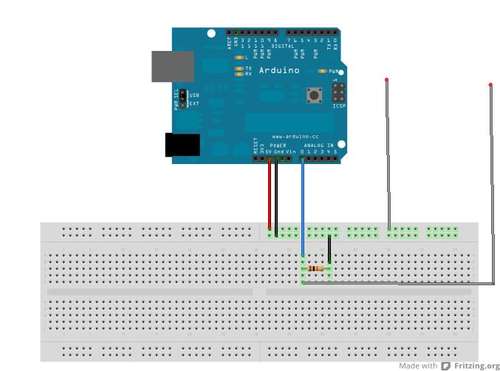
The hardware consists of nothing more than an Arduino, a 10K resistor, wire and some tin foil. (You didn’t use ALL your foil for your hat, did you?) The device operates on the galvanic skin response (GSR) principle and detects changes therein via a foil band around your finger. The ends of the band are connected between the two open leads as depicted in the above diagram, with the Arduino taking readings on Analog pin 0. Readings are displayed on your PC as a graph using Processing.

All source code (both Arduino and Processing sketches) is contained in the Arduino Communications/Graph example within the Arduino IDE.

Via Mad Science/wonderhowto.

Free PCB coupon via Facebook to 2 random commenters

Every Friday we give away some extra PCBs via Facebook. This post was announced on Facebook, and on Monday we’ll send coupon codes to two random commenters. More PCBs via Twitter on Tuesday and the blog every Sunday.

This week we have a guest PCB, the Bitlair PCB.  Use your coupon to pick this PCB, or any other in the free PCB drawer.

Don’t forget there’s free PCBs three times a every week:

Continue reading “Free PCB coupon via Facebook to 2 random commenters”

Week in (p)review April 20, 2012

Here’s a summary of major developments over the last week. Free PCB Friday is coming up soon.

Coming up:

  • A new workshop video next Thursday
  • Free PCBs via Facebook on Friday
  • App notes on the weekend
  • Free PCB Sunday
  • New 3D model on Monday
  • Free PCBs via Twitter on Tuesday
  • Weekly roundup and preview every Friday

What are you hacking this week?

Global Geek Tour: Shenzhen Hua Qiang Bei market tour roundup

Dangerous Prototypes tours the biggest electronics market of all, the Hua Qiang Bei market in Shenzhen, China. This is the third and biggest market on our Global Geek Tour. Be sure to check out Akihabara in Tokyo and Cheonggyecheon in Seoul too.

Don’t forget our wiki of resources and map layers to help plan your next geek tour or Maker Faire.

AVR emulating ARM Cortex M0

First, an AVR that boots Linux. Now a Cortex M0 emulator for the ATtiny:

I like writing emulators. Since my last one (ARM emulator that booted linux), I was wondering how much faster one could emulate an ARM cpu on an atmega device. The C-language core netted 10KHz. This time I decided to reduce the scope of the problem, and try to use a smaller device. So the goal was then: Cortex-M0 emulator on an ATTiny85.

Via the forum.