0-30V laboratory power supply

3D_pcb_top_first

Hare’s the 0-30V laboratory power supply project by Arief Laksono of Electronics Lab:

This project is based on the 0-30 VDC Stabilized Power Supply with Current Control 0.002-3 A and a new PCB layout is introduced here. It’s a stabilized power supply with variable output voltage in the range 0-30Vdc (33Vdc peak) – and variable current 3A and is ideal for your laboratory power supply.

TinyPrime project based on ATTiny13A

TinyPrime.preview

Spacewrench over at Dorkbotpdx writes:

This is a rebuild of the TeensyPrime project I built a while ago, using a separate breadboard that’s almost too small (I had to use magnet wire to fit some of the connections) and a microcontroller that’s almost too small. The ATTiny13A is a neat chip: AVR with 1K of flash, 64 bytes of RAM and 64 bytes of EEPROM. I programmed it using a Teensy-2.0-based waldo running Ward Cunningham’s TXTZYME.
The programming for this is actually kind of interesting. Every time you push the button, the AVR retrieves the currently-displayed number (which is stored in EEPROM), and then increments it, clicks the counter, and tests for primality. If the number isn’t prime, it increments and clicks again. When a prime number is reached, it stops and waits for another button press.

Check out the video after the break. Continue reading “TinyPrime project based on ATTiny13A”

Multitask scheduler for MSP430F5529 launchpad

In this video Jeffrey Antony demonstrates his multitask scheduler for MSP430F5529 launchpad:

I have checked in the code to my github repo. Its an completely open source scheduler. Feel free to use it and learn more. I have made the code self explanatory. Enjoy!
There are three tasks – first task for blinking the red LED at a particular rate, the second for blinking the green LED at a particular rate and last one for reading both the buttons. When you press the button, you could toggle the blinking of both the LED’s. Buttons are not properly detected due to software debouncing issue.

Mini Quad – build a FPV250 mini-H quadcopter

mini-quad-feature-600x540

Oscar Liang built a  FPV250 mini-H quadcopter and wrote a post on his blog detailing it’s assembly:

Having built a mini quad before running on 2S, although it was very easy to control and stable, I was not particularly happy with the power. I cannot fly too fast, neither doing flips and acrobatics. This time I will be using the Hobbyking mini quad frame, with the Cobra 1960KV motors on 4S battery. This will be light weight, yet really powerful. Although the FPV250 Mini Quad Frame is X configuration, by adding a long frame kit (Diatone Cage), it looks similar to a H-quad.

Here is my current Specs:
-FPV250 Quadcopter Frame with Cage Long Frame Kit
-Cobra 2204 1960KV Brushless Motors
-12A Blue Series ESCs with SimonK Firmware
-Gemfan 5030 Propellers
-KK2.1.5 Flight Controller with Stevis Firmware
-Frsky DJT Transmitter and D8R-XP Receiver
-Turnigy 9X with er9X Firmware
-SONY SUPER HAD 600TVL CCD Camera – PZ0420 with 2.8mm Lense (FPV)
-Mobius Wide Angle Lense (Recording)
-Hobbyking e-OSD with cl-OSD Firmware
-Boscam 5.8GHz Video Transmitter VTX
-Turnigy Nano Tech 4S Battery 1300mAh/1800mAh
-Weight ~ 680g
-Flight time ~ 9 minutes

850 MHz scanner preamplifier / filter project

850_MHz_Box_Inside

KF5OBS writes:

This article shows how to use off-the-shelf parts to improve the performance of a radio scanner in the 800 – 900 MHz band. Furthermore, it shows how to expand radio coverage by using two different receive antennas at the same time.
For some reason, my new BCD996XT scanner wasn’t working as expected on the statewide digital (APCO 25) radio system. Since this radio system is the primary reason why I got this new scanner, I had to come up with a solution. In addition, I really wanted to expand my receive coverage geographically. This article shows how to improve receive signal strength, greatly increase geographical coverage and reduce out-of-band interference.

Omnivision OV9650 Breakout

DSC03733

Mux blogged about his breakout for the OV9650, all files are available here:

I made this breakout for the OV9650 a while ago, and I’ve been waiting to test it before sharing, I finally had the chance to do so, I used an FPGA this time for testing, and here’s the result.
The breakout has two SOT23 LDOs for the sensor’s core, digital and analog supplies and requires a single external 3.3v supply, note that most sensors have internal regulators for the core supply, so technically you only need one, anyway, those LDOs should be fairly easy to source, their exact voltages depend on the sensor used. The board is compatible with a few other Omnivision sensors, such as the OV9655, OV7660, OV2640 etc… however, make sure it has the same pinout…

Serial AVR and PIC programmer

3D_PCB_top_first

Dr. Ayman Shalaby over at Electronics Lab posted another project, a serial AVR and PIC programmer:

This is a dual MCU programmer which supports both AVR and PIC mcu and there is a switch to select between them.
It’s easy to manufacture and have only through hole parts.

Features
– RS232 Serial interface
– AC-DC powered
– MAX232 interface
– standard programming sockets for PIC and AVR
– easy to build, all component are TH parts
– 74CA00 for protection
– LED indicators for VPP, TxD, RxD, Power
– Compatible with PonyProg and similar software
– 10 Pin ICSP for AVR (Miso, SCK, Mosi, Reset, GND, VCC)
– 5 Pin ICSP for PIC (VPP, VDD, VSS, PGD, PGC)

#FreePCB via Twitter to 2 random RTs

Shrinking-tubes-kit

Every Tuesday we give away two coupons for the free PCB drawer via Twitter. This post was announced on Twitter, and in 24 hours we’ll send coupon codes to two random retweeters.

Don’t forget there’s free PCBs three times a every week:

  • Hate Twitter and Facebook? Free PCB Sunday is the classic PCB giveaway. Catch it every Sunday, right here on the blog
  • Tweet-a-PCB Tuesday. Follow us and get boards in 144 characters or less
  • Facebook PCB Friday. Free PCBs will be your friend for the weekend

Some stuff:

  • Yes, we’ll mail it anywhere in the world!
  • Check out how we mail PCBs worldwide video.
  • We’ll contact you via Twitter with a coupon code for the PCB drawer.
  • Limit one PCB per address per month please.
  • Like everything else on this site, PCBs are offered without warranty.

We try to stagger free PCB posts so every time zone has a chance to participate, but the best way to see it first is to subscribe to the RSS feed, follow us on Twitter, or like us on Facebook.

Bus pirate used to hack into a car

Nilsson writes to inform us that he spotted a Bus Pirate in a video from Vice News, “How to hack a car: Phreaked Out (episode 2)”

From his laptop, he was able to manipulate the car’s engine, brakes and security systems by wirelessly tapping into the Controller Area Network, or CAN bus, network. Without getting too deep into the details—both for legal reasons and due to my own training-wheel knowledge of such things—he was able to do so by implementing some off-the-shelf chips, a third party telematic control unit, a GSM-powered wireless transmitter/receiver setup, and a significant amount of know-how he’s accrued over the years.

Via the contact form.

Get your own handy Bus Pirate for $30, including world-wide shipping. Also available from our friendly distributors.

LCD clock version 2 – part II

lcdclockv2final_0002

Here’s an update on Kevin Rye’s LCD clock we covered previously.  Source files are available here, for direct download LCD-Clock-V2-Source.zip:

Once all the components and headers were soldered in, I attached my Arduino and configured it as an ISP. I then burned the bootloader for an Arduino Uno.
I then connected my FTDI programmer and uploaded the blink sketch.Success!
Wow, that LED is super bright! It’s actually blinding and kind of hard to look at. With that, I swapped out the resistor for a 1K one in order to bring the brightness down.
Knowing that the Atmega worked, it was time to solder in the rest of the components, except for the display. Again, I don’t want to come this far and then waste a $15 LCD.

DIY NAND Flash reader


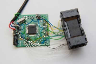
SpriteMods has published their design for a DIY NAND flash reader.

When security-testing the ‘secure’ USB-sticks I got my hands on in the past, I needed a way to directly read the NAND-flash these sticks use to store the data on. For that, I created a quick hack: a NAND-reader consisting of a small PCB the flash had to be soldered on and a parallel port interface. There was no voltage conversion apart from some resistors to limit the current from the 5V parallel port to the 3.3V flash chip and the software was a horrific hack, but the contraption worked: I now had a tool to read out NAND flash, even if it was tied together with the solder and the software equivalent of lots of duckttape.

Their latest design uses USB instead of a parallel port, accomplishing this using a FT2232H module. (This module retails fo around $27 from Digikey.

For the schematic and source code, visit SpriteMods.

Simple LED driver/constant-current source 20 mA

F9KEIFWHNVJ1K1X

Another Instructable by Jan Henrik,  a constant-current source which gives 20mA at the output.  He writes:

It is a circuit, which limits the current to 20mA, what allows us to drive any normal led, without calculating a resistor, you can just plug the led in and see it emitting light…
Also this allows us to test LED´s, to test the polarity(if there are no marks on the LED) and also it allows us to figure out the perfect forward voltage of the LED.
We can measure it, when we plug the LED in and measure the Voltage drop at the LED. Then you will have the perfect forward voltage…

This is a Great project for beginners, it´s easy to solder, it doesn’t require expensive parts, no ic´s…
Or you can use it for circuits with a variable input Voltage, because the input voltage does not change the output voltage, until it reaches the limits of the circuit

Via the contact form.

EGYDuino – Arduino compatible board

3D_PCB_EgyDuino

Dr. Ayman Shalaby over at Electronics Lab has posted an article describing EGYDuino, an Arduino compatible board that can be build using home process:

EGYDuino is a DIY Arduino clone made on a single sided PCB board. It’s simple and cheap to build using home PCB fabrication methods and it’s 100% compatible with Arduino.

The easy peasy stepper driver/stepper motor test circuit

perf

Rohit Gupta writes:

I made a very easy to make stepper driver and motor tester that could be useful to people working with steppers for 3D printers or CNC.
I saw an article a while back here on DP and HackADay itself that used a controller (ATiny45 i guess). I thought it would be useful to do it with a 555 timer.

Via the contact form. Continue reading “The easy peasy stepper driver/stepper motor test circuit”

Bubble display alarm clock

IMG_3538_1600x1200_85

Markus Gritsch build another bedside table alarm clock, the schematic and source code is available here:

recently some vintage bubble displays popped up at various places [1][2], so I felt the urge to build another bedside table alarm clock, this time a really tiny one, roughly the size of an AAA battery.

Check out the video after the break. Continue reading “Bubble display alarm clock”

app note: Digital Potentiometers: Frequently Asked Questions

ap_AD_AN1291

FAQ on Analog Device’s digital Potentiometers. App note here.

A digiPOT is a digitally controlled resistor that changes the impedance between the terminals and wiper depending on the code loaded in the RDAC register. Digital potentiometers avoid the problems that mechanical potentiometers face, such as physical size and wear and tear, as well as sensitivity to vibration, temperature, and humidity.
This application note answers a series of frequently asked questions (FAQs) about Analog Devices, Inc., digital potentiometer (digiPOT) products.

Free PCB Sunday: Pick your PCB

KHOS-2-3-4-5-6P

We go through a lot of prototype PCBs, and end up with lots of extras that we’ll never use. Every Sunday we give away a few PCBs from one of our past or future projects, or a related prototype. Our PCBs are made through Seeed Studio’s Fusion board service. This week two random commenters will get a coupon code for the free PCB drawer tomorrow morning. Pick your own PCB. You get unlimited free PCBs now – finish one and we’ll send you another! Don’t forget there’s free PCBs three times every week:

Continue reading “Free PCB Sunday: Pick your PCB”

app note: How to Oversample 5 MSPS, 18-Bit/16-Bit Precision SAR Converters to Increase Dynamic Range

ap_AD_AN1279

Here’s how you can maximize your ADC’s Dynamic Range by oversampling, an app note from Analog Devices.

One of the ways to achieve a higher dynamic range is to oversample the converter to accurately monitor and measure both small and large input signals from the sensors. There are a number of other ways to increase the dynamic range of an analog-to-digital converter(ADC), such as using programmable gain amplifiers or operating multiple ADCs in parallel and digital postprocessing the out put to get the averaged result. However, some designers may find these methods cumbersome or impractical to implement for their systems, mainly due to power, space, and cost constraints. This application note focuses on the oversampling of high throughput, 5 MSPS, 18-bit/16-bit precision successive approximation register (SAR) converters by implementing a straightforward averaging of ADC output samples to increase the dynamic range.

Poor maker’s IR receiver #2

PoorMansIRreceiver2_cc-300x218
As promised, the AnalysIR crew has released their design for a simple IR receiver, this time using the Arduino.

Our recent post about the silver bullet IR receiver proved very popular and we promised that we would follow-up with another variant of the poor maker’s Infrared receiver. This time we are using an IR LED (emitter), 2 resistors and any standard Arduino. You will also need to download the Arduino code, compile and upload it. One of the most common problems encountered when trying to decode IR signals is that makers don’t always have the appropriate IR receiver for the job in hand or have to wait for one to be delivered by mail. Here we present an affordable method to allow you to use any IR emitter (LED) as a receiver and as a bonus we are publishing the Arduino code to make it all work.

Via the contact form.