Counter project recorded in C

counter44

Ricardo of Electropepper writes:

So i’ve decided to rewrite the code in C language using the MikroC compiler for the Counter project.
I have chosen MikroC compiler for its easy of use and good documentation, unfortunatelly the IDE editor simple sucks big time, so it really is good for me to tolerate it.
I also got recently some professionally finished PCB’s.
This is a part of the Counter project.

Check out the video after the break. Continue reading “Counter project recorded in C”

Turning the Freedom board into a Logic Analyzer

i2c-capture-with-decoder

Erich Styger of MCUonEclipse writes:

I think the most important tool for a firmware engineer is a Logic Analyzer. I always have one on my desk. Working in different locations, sometimes I forget to carry it with me. And for sure I would need it. To buy another one to compensate my laziness? Or maybe there is another solution? And here I stumbled over an article about the Logic Sniffer project recently: it is about an open source logic analyzer hardware and firmware project. What a cool idea! Why not using my FRDM-KL25Z Freedom board as a Logic Analyzer? Heck, that would be awesome :-)

Digital audio amplifier with PLL synthesized FM radio

DFMRADIO_FINAL_SMALL

Another open source hardware project by Dilshan Jayakody the digital audio amplifier with PLL synthesized FM radio:

This is high quality stereo digital audio amplifier with PLL synthesized FM radio receiver. Some of the high level specifications of this receiver are listed in below:

  • Audio output power: 4W + 4W (with 8ohm speakers)
  • Input sources: FM and 3 external stereo line inputs
  • FM frequency range: 88.00MHz – 108.9MHz
  • Supply voltage: 12V – 15V (2A current source is recommended)
  • Tone control options: Bass, Treble and Loudness control
  • Bass / Treble boost: 14dB
  • Bass / Treble cut: 14dB
  • Station memory: Preset 10 FM radio stations
  • FM tune options: Auto and Manual with 25 kHz steps

All the source codes and design files are available here.

Hacking the Java Debug Wire Protocol (JDWP)


Christophe Alladoum has posted a tutorial on the IO Active Labs Research blog on the Java debug wire protocol and its insecurities. He explains, “In this post, I will explain the Java Debug Wire Protocol (JDWP) and why it is interesting from a pentester’s point of view. I will cover some JDWP internals and how to use them to perform code execution, resulting in a reliable and universal exploitation script. This post does not reveal any 0-day exploits, but instead thoroughly covers JDWP from a pentester/attacker perspective.”

Official documentation explaining the Java debug wire protocol can be found on the JDWP page at Oracle.

#FreePCB via Twitter to 2 random RTs

probecable-yellow Every Tuesday we give away two coupons for the free PCB drawer via Twitter. This post was announced on Twitter, and in 24 hours we’ll send coupon codes to two random retweeters. Don’t forget there’s free PCBs three times a every week:

  • Hate Twitter and Facebook? Free PCB Sunday is the classic PCB giveaway. Catch it every Sunday, right here on the blog
  • Tweet-a-PCB Tuesday. Follow us and get boards in 144 characters or less
  • Facebook PCB Friday. Free PCBs will be your friend for the weekend

Some stuff:

  • Yes, we’ll mail it anywhere in the world!
  • Check out how we mail PCBs worldwide video.
  • We’ll contact you via Twitter with a coupon code for the PCB drawer.
  • Limit one PCB per address per month please.
  • Like everything else on this site, PCBs are offered without warranty.

We try to stagger free PCB posts so every time zone has a chance to participate, but the best way to see it first is to subscribe to the RSS feed, follow us on Twitter, or like us on Facebook.

Drum light trigger that uses leds, a NE555 timer and a piezo transducer

led_drum_light_trigger

Davide Gironi writes:

This circuit is a Drum Light Trigger.
It uses a piezo transducer that reacts to drum vibration, and a NE555 timer to setup the light time.
There are two trimmer pot, one to setup the sensibility of the vibration, the other to set how long the LED light will be active.
This design is a small makeover of a circuit i’ve printed from an online image, unfortunately i can not recover the original author.

Check out the video after the break. Continue reading “Drum light trigger that uses leds, a NE555 timer and a piezo transducer”

ATtiny85 POV display

FH5WY3HHVWWNBR9

Vishalapr made this Instructables detailing the build of his DIY POV Display based on ATtiny85:

The first time I saw a POV (Persistence Of Vision) display was on a show called FAQ on TV. The POV display consisted of an oscillating shaft with 6 LED’s mounted on the end of the shaft.
Since then I have always wanted to make one myself, I tried making one about 2 months ago with an oscillating shaft myself but I was not successful as the speed of the shaft was too low for the POV display to work. Now I decided to make the POV display with just a DC Motor instead of an oscillating shaft as they are much cheaper and easily available compared to the shafts.
In this instructable I will show you how to make the POV Display yourself!
This is a very simple project both on hardware and software (coding) areas. It costed me only about 5$ to make it from start to finish!

Check out the video after the break. Continue reading “ATtiny85 POV display”

Read serial data without PC on GLCD

IMG_20140607_092308789-1024x575

Hemal Chevli wrote an article detailing his new tool the GLCDTerm that reads serial data without PC on GLCD:

I’m calling it GLCDTerm(spin-off from GTKTerm), this handy tool reads TTL serial data and displays it on GLCD. This is the first time I’ve used a GLCD in any of my projects. It runs on m328 using arduino bootloaer and the awesome GLCD library. I first made a prototype on one of my arduino clones, Below is the video running diagnostics program.

Check out the video after the break.

Continue reading “Read serial data without PC on GLCD”

USB to Serial converter using AVR microcontroller

3D_PCB_SMD_first

Yet another great project by Dr. Ayman Shalaby of Electronics Lab, a USB to Serial converter using an ATMEL AVR microcontroller:

This project is a USB to Serial converter using an ATMEL AVR microcontroller. There are two version of the converter, one with SMD parts and another with TH parts. The mcu used is an ATmega8 and USB communication is done using software on AVR mcu. It’s based on the software USB implementation of AVR-CDC. Firmware can be downloaded from the download section of CDC-RS232.

DIY prototyping board with 3.3V, 5V, 12V and -12V built in power supplies

diy-prototyping-board-header

Electro Labs’ new project the DIY prototyping board with 3.3V, 5V, 12V and -12V built in power supplies:

This DIY Prototyping Board is designed to provide all the most used supply voltages that a designer will need during prototyping a circuit. The switching power supplies on the board output 3.3V, 5V, 12V and -12V rated at 1A independently. In addition those there are two precise voltage references at 5V and 2.5V provided especially for op-amp based applications.

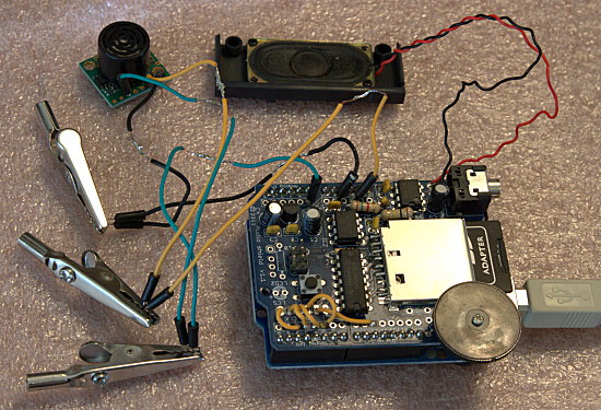
Build an Arduino based sonic pest repeller


Just in time for Summer, here’s a design for a sonic pest repeller. Carla Schroder developed this project which uses an Arduino Uno along with the WAVE shield and a Maxbotix ultrasonic rangefinder. This simple yet reportedly effective design senses critters nearing your garden plot and plays sound files (stored on an SD card) intended to irritate and repel the invaders.

Via Linux.com.

Free PCB Sunday: Pick your PCB

buspiratev38 We go through a lot of prototype PCBs, and end up with lots of extras that we’ll never use. Every Sunday we give away a few PCBs from one of our past or future projects, or a related prototype. Our PCBs are made through Seeed Studio’s Fusion board service. This week two random commenters will get a coupon code for the free PCB drawer tomorrow morning. Pick your own PCB. You get unlimited free PCBs now – finish one and we’ll send you another! Don’t forget there’s free PCBs three times every week:

Continue reading “Free PCB Sunday: Pick your PCB”

app note: Isolating I2C interfaces

ap_AD_AN913

an I2C isolation solution from Analog Devices, app note can be found here.

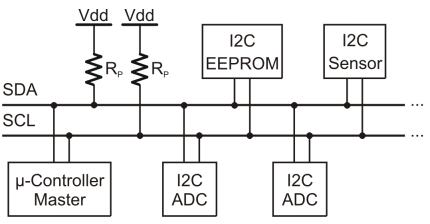
The Inter-Integrated Circuit (I2C®) bus is a two-wire bidirectional bus used for low speed, short-distance communication between integrated circuits. Developed by Philips 1980 in the early 1980s for use amongst ICs on a single board, I2C today is increasingly being used in multiboard applications as new bus extensions and control devices help overcome the original 400 pF maximum allowable load capacitance.
This application note provides a brief overview of the I2C bus (focusing on its physical layer), discusses the challenges in isolating I2C interfaces, and describes iCoupler® solutions for isolating I2C interfaces.

app note: Generic data transfer using USB HID

ap_nordic_nAN22

Here’s an app note from Nordic Semiconductor on using nRF24LU1+ USB HID communication.

The Universal Serial Bus is the de factor inustry standard for the connection of computer peripherals, with approximately two billion sold devices every year. The success of USB is in large part due to its end product ease of use. However, such simplicity comes at a price, as the developer is often burdened with creating complex USB drivers. Fortunately, there is a simpler way to provide devices with USB support.

This application note primarily describes how to use HID to transfer data between a Microsoft Windows application and the nRF24LU1+. It also goes into some detail about the example application, an over-the-air firmware flash updater for the nRF24LE1 using the combined USB and RF features of the nRF24LU1+.

9V to 48V DC-DC converter

3D_PCB_first-e1401962309482

Konstantin Dimitrov over at Electronics Lab writes:

This project is a 8-12Vdc to +48Vdc DC-DC converter based on MC34063 switching regulator.
It’s a simple project of a DC-DC converter to make a phantom power supply for professional microphones. It can deliver 15-20mA at 48VDC. It ‘s based on MC34063 DC-DC step-up, step-down and boost converter. Input is between 8-12V DC and the output +48VDC/10-20mA.

DEFCON 21 video: Decapping Chips the Easy Hard Way


In this presentation from DEFCON 21, Adam “Major Malfunction” Laurie and Zac Franken of Aperture Labs go hardcore with chip analysis.

For some time it has been possible to discover the inner workings of microprocessors with the help of a microscope and some nasty chemicals such as fuming nitric acid. However, unless you have access to a university or work science lab, this is beyond the reach of most hackers, and, even it were to be attempted, difficult and potentially extremely dangerous.

In this talk we will go through our own adventures in tackling the issue from the point of view of the back-room hacker/researcher, and how we have solved many of the problems using only tools and devices that were freely and cheaply available from online sources such as Ebay.

Further description can be found at Zacsblog on Aperture Labs.

Free PCB coupon via Facebook to 2 random commenters

KHOS-2-3-4-5-6P Every Friday we giveaway some extra PCBs via Facebook. This post was announced on Facebook, and on Monday we’ll send coupon codes to two random commenters. More PCBs via Twitter on Tuesday and the blog every Sunday. Don’t forget there’s free PCBs three times every week:

Continue reading “Free PCB coupon via Facebook to 2 random commenters”

Chipstomp assembly – Analogue side

img_0744 (1)

We previously covered Catmacey’s Chipstomp digital side. Now he built the Chipstomp’s analogue side:

It’s done.  I’ve assembled the analogue side of the Chipstomp and finally have a fully working device.  There were no errors to fix this time which was a nice surprise.  Just lots of fiddly 0805 surface mount components to place.

Check out the video after the break. Continue reading “Chipstomp assembly – Analogue side”