App note: Applications of zero voltage crossing optically isolated triac drivers

an_fairchild_AN-3004

App note from Fairchild Semiconductors about their zero voltage crossing isolators. Link here (PDF)

The zero-cross family of optically isolated triac drivers is an inexpensive, simple and effective solution for interface applications between low current dc control circuits such as logic gates and microprocessors and ac power loads (120, 240 or 380 volt, single or 3-phase).

This paper describes the operation of a basic driving circuit and the determination of circuit values needed for proper implementation of the triac driver. Inductive loads are discussed along with the special networks required to use triacs in their presence. Brief examples of typical applications are presented.

App note: Using the Configurable Logic Cell (CLC) to interface a PIC16F1509 and WS2811 LED driver

apps1

An application note (PDF!) from Microchip on how to use CLC to interface a PIC16F1509 and WS2811 LED driver:

The Configurable Logic Cell (CLC) peripheral in the PIC16F1509 device is a powerful way to create custom interfaces that would otherwise be very difficult. One example is the single-wire PWM signal, used by the WS2811 LEDs, well known in LED video display systems. This application note will provide a simple demonstration of a WS2811 LED Strip driver.

A Christmas star with Neopixel LEDs

pics-Star with Neopixel LEDs

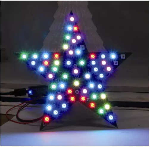
A geeky Christmas decoration made with 56 LED Neopixel and controlled via an Arduino Micro board from Open Electronics:

Let’s take a look, therefore, at the project’s electrical section, that is essentially composed of a set of 56 Neopixel LEDs, that have been arranged so to form two concentric stars; the first 35 RGB LEDs (out of 56) form the bigger, external star, while the other 20 ones form the smaller and internal star. The LED number 56 is placed exactly at the center of the printed circuit board, that has the shape of a five-pointed star.
The Neopixel LEDs are connected in cascade but powered in parallel; such a configuration enables to address each single LED and to individually choose the colour; among the possible hues, the 256 possible combinations for each primary colour (therefore we have 256x256x256 combinations!) determine a total of 16,777,216 colours: that’s what one would call true colours!

More info at Open Electronics’ Open Source projects page.

Free PCB coupon via Facebook to 2 random commenters

BP

Every Friday we give away some extra PCBs via Facebook. This post was announced on Facebook, and on Monday we’ll send coupon codes to two random commenters. The coupon code usually go to Facebook ‘Other’ Messages Folder . More PCBs via Twitter on Tuesday and the blog every Sunday. Don’t forget there’s free PCBs three times every week:

Continue reading “Free PCB coupon via Facebook to 2 random commenters”

Intel(r) Quark(tm) micrcontroller D2000 based Environmental sensors board

pics-D2000 - Assembled Board 2 (1)-600

Sergey Kiselev designed and built an Intel Quark D2000 micrcontroller based Environmental sensors board:

This is a fairly small (51 x 51 mm) board, equipped with a low power Intel Quark D2000 microcontroller, and several sensors (accelerator, temperature, humidity, atmospheric pressure), as well as a mikroBUS compatible header and a Grove compatible connectors, that can be used to connect additional sensors, memory, or radio modules. The board can be used to monitor the environment conditions, and store or transmit the data to a remote system for further processing.

More details at Sergey’s Projects page.

The Bitx40 project

pics-Bitx40-600

Pete Juliano, N6QW, has been working on building the Bitx40 project:

At this stage the hardware is mounted and previously I had programmed the Arduino/AD9850 which will be used for the LO. The case was something store bought about 6 years ago and is nothing more than a 6X10X2 aluminum chassis painted two tone. The front panel is of course a cool blue color.
But there is another side to this project in that I will de doing a Skype presentation to a local ham club in mid January and in preparation for that Bitx40 pitch have created a series of web pages on “How to take the Bitx40 as supplied and make it like the photo above. Here is the link to the web “Resource Page

Full details at Pete Juliano’s blog.

Teardown of a Vivitar Rapid battery charger

pics-charger-600

Kerry Wong did a teardown of a Vivitar rapid battery charger for the NP-FW50 lithium-ion battery pack used in Sony A6000 digital camera:

The circuit board itself though looks surprisingly clean and well designed. It does not use any dedicated lithium ion battery charging ICs however. Rather a MC34063A buck/boost DC-DC converter chip is used to provide the current limited 8.4V constant voltage. This arrangement is less ideal then the typical lithium ion battery charging technique. Typically, the charging current is held constant until the voltage reaches a certain threshold and then the charger switches to constant voltage mode. Once the charging current drops under a predetermined threshold the charging is done. The charging current under constant voltage charging however, monotonically decreases from the get go so it usually takes much longer to obtain a full charge. But the good news here is that overcharging is unlikely as the charging voltage is fixed to the correct battery terminal voltage.

More details at Kerry Wong’s blog.

Check out the video after the break. Continue reading “Teardown of a Vivitar Rapid battery charger”

#FreePCB via Twitter to 2 random RTs

BP-600x373

Every Tuesday we give away two coupons for the free PCB drawer via Twitter. This post was announced on Twitter, and in 24 hours we’ll send coupon codes to two random retweeters. Don’t forget there’s free PCBs three times a every week:

  • Hate Twitter and Facebook? Free PCB Sunday is the classic PCB giveaway. Catch it every Sunday, right here on the blog
  • Tweet-a-PCB Tuesday. Follow us and get boards in 144 characters or less
  • Facebook PCB Friday. Free PCBs will be your friend for the weekend

Some stuff:

  • Yes, we’ll mail it anywhere in the world!
  • Check out how we mail PCBs worldwide video.
  • We’ll contact you via Twitter with a coupon code for the PCB drawer.
  • Limit one PCB per address per month please.
  • Like everything else on this site, PCBs are offered without warranty.

We try to stagger free PCB posts so every time zone has a chance to participate, but the best way to see it first is to subscribe to the RSS feed, follow us on Twitter, or like us on Facebook.

Zeta 2 single board computer

pics-zeta2-complete-600

Scott Baker has a nice write-up on building a Zeta v2 single board computer designed by Sergey Kiselev:

A few of the features of the Zeta 2:

  • 512K Flash Memory, allows CP/M to be booted from Flash, and mounts Flash as a CP/M disk including many tools (assembler, editor, …)
  • 512K Flash ROM, can be used as RAM Disk. Supports battery backup.
  • 16550 UART provides a single serial port
  • 8255 PIO supports up to three 8-bit serial ports
  • Dallas 1210 Real-Time Clock
  • WD37C65 floppy controller, easily supports 3.5″ PC Floppy Drives

Project info at Scott Baker’s blog.

Check out the video after the break.

Continue reading “Zeta 2 single board computer”

Homebrew WiFi shield

pics-Banner-600

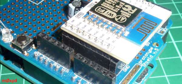
m0xpd has published a new build, the homebrew WiFi shield:

Having just finished development of the new m0xpd / Kanga ESP8266 – AD9834 board, I find myself with a few WiFi components knocking about on the bench – so I figured it would be fun to try to make a WiFi shield for an Arduino…
Using an ESP8266 (in a module, such as an ESP-12) as a WiFi shield for an Arduino is a little like using the proverbial ‘steam hammer to crack a nut’ – but these modules are frighteningly cheap and I do want a WiFi shield (which are surprisingly expensive).
I have a spare ESP-12 module on a nice breakout board with 0.1 inch pitch headers, just crying out to be used once again (it having done service in the early stages of the development of the connected beacon etc)

More info at m0xpd’s blog.

Semiconductor radioactivity detector

pics-IMG_2665-600

Robert Gawron has been working on a semiconductor radioactivity detector project:

Currently I’m trying to make a working version of a radioactivity detector that uses semiconductor as a sensor. It’s a different approach than Geiger-Muller detectors, more complicated, but also much more interesting.
While Geiger-Muller counters can only provide information about the amount of particles in a period of time, semiconductor detectors can also measure their energy, so it’s possible to say much more about the nature of observed ionizing radiation. Some of the disadvantages of these detectors are that they are more expensive, complex and sensitivity may degrade over time.

More details at Robert Gawron’s blog.

LED candle effect: Tear down and decap of a controller

A teardown video from Electronupdate:

A dollar store item which implements a flickering candle effect using and LED. A look at the technology: linear feedback shift register or ROM based? Let’s decap the controller and take a look at the silicon die to find out!

More details at Electronupdate blog.

Free PCB Sunday: Pick your PCB

BP-600x373

We go through a lot of prototype PCBs, and end up with lots of extras that we’ll never use. Every Sunday we give away a few PCBs from one of our past or future projects, or a related prototype. Our PCBs are made through Seeed Studio’s Fusion board service. This week two random commenters will get a coupon code for the free PCB drawer tomorrow morning. Pick your own PCB. You get unlimited free PCBs now – finish one and we’ll send you another! Don’t forget there’s free PCBs three times every week:

Continue reading “Free PCB Sunday: Pick your PCB”

App note: Transponder coils in an RFID system

Doc397_TranspondersinRFID

A short application note from Coilcraft about transponder coils. Link here (PDF)

Radio Frequency Identification (RFID) is the system of using radio signals to send information identifying a particular situation or item. It can be used to track and locate any item including material, people and animals.

The RFID transponder coil is part of the coupling device and acts as the transmitting antenna. The key specifications of the transponder coil are sensitivity and read distance, however, the inductance of the transponder coil directly influences the sensitivity and the read distance. Generally, a higher inductance provides greater sensitivity resulting in a longer read distance. The manufacturer of the tag usually specifies the inductance of the coil to be used. The read distance is defined as the maximum distance from the reader that the transponder responds to the reader’s magnetic field.

App note: Signal transformer application and specification

doc157_SigXfrmApp

Application note from Coilcraft discussing the wideband transformer and the autotransformer. Link here (PDF)

In the simplest sense, a transformer is two or more windings coupled by a common magnetic field. This magnetic field provides the means to pass voltages and currents from one winding (primary) to the other winding (secondary). Magnetic flux is created when an alternating current flows through a winding.

Transformer have many uses, such as isolation of DC currents, voltage and current transformations, and impedance matching. The type of signals to be transferred from the primary to secondary windings dictate the type of transformer that should be used in an application. For instance, a transformer needed to provide DC isolation between two windings carrying large amounts of currents would be designed differently from a transformer that needs to provide an impedance match to a small signal communications network. In this article, the emphasis will be on two types of signal transformers that are designed specifically for the transmission of data at low power levels with DC isolation (the wideband transformer) and those designed to be non-isolating (the auto transformer). These types of transformers are not limited to low power capabilities, but the emphasis here is for use in communication and small signal applications.

CTCSS fingerprinting: A method for transmitter identification

plot-lock

Oona Räisänen from Absorptions wrote an article about experimenting with CTCSS fingerprinting:

Identifying unknown radio transmitters by their signals is called radio fingerprinting. It is usually based on rise-time signatures, i.e. characteristic differences in how the transmitter frequency fluctuates at carrier power-up. Here, instead, I investigate the fingerprintability of another feature in hand-held FM transceivers, known as CTCSS or Continuous Tone-Coded Squelch System.

More details at Absorptions site.

Free PCB coupon via Facebook to 2 random commenters

BP

Every Friday we give away some extra PCBs via Facebook. This post was announced on Facebook, and on Monday we’ll send coupon codes to two random commenters. The coupon code usually go to Facebook ‘Other’ Messages Folder . More PCBs via Twitter on Tuesday and the blog every Sunday. Don’t forget there’s free PCBs three times every week:

Continue reading “Free PCB coupon via Facebook to 2 random commenters”

Brute force computation for cheap log digital potentiometer

motivation

Michael from Acidbourbon writes:

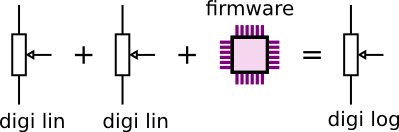
This article covers the attempt to build a digital logarithmic potentiometer out of two linear potentiometers. The benefits of this concept

  • Linear digital potentiometers can be easily procured and don’t cost much
  • There are IC packages with two or four modules inside anyway
  • The resulting logarithmic potentiometer is very flexible in terms of number of steps and steepness of the attenuation function

Full details at Acidbourbon homepage.

Serial seven segment LED display shield

pics- serial-seven-segmentLED-600

Raj over at Embedded Lab has just finished a new project article about a serial seven segment LED display shield:

Seven segment LED displays are brighter, more attractive, and provide a far viewing distance as well as a wider viewing angle compared to LCD displays. This project describes a serial seven segment LED display shield for Arduino Uno or compatible boards. The shield consists of eight 0.56″ seven segment displays that are driven by one MAX7219 chip. The shield also features a light dependent resistor (LDR) to implement adaptive brightness control to the LED displays. The LDR output can be fed to A0 or A1 analog input channel of Arduino to read the surrounding illumination level. Arduino can then use that information to adjust the brightness of the LED displays. A demo code and Eagle CAD files are also provided in the latter part of the article.

Full details at Embedded Lab blog.

G-code controlled drawing plotter

pics-DrawingPlotter -600

A how-to on making a 2 axis, G-code controlled drawing plotter from TheSuperSewcio, project instructables here:

Here I’ll show you how to make 2 axis, gcode controlled drawing plotter.
I’ve already made a delta 3D printer which is awesome, the only thing that wasn’t made by me was the Arduino program. This program was very long and complicated, so I’ve downloaded it from the Internet. I’ve started to think if I am able to also make it myself. But why should I start with something so hard, firstly let’s make something easier – Plotter!

Check out the video after the break. Continue reading “G-code controlled drawing plotter”