
A DIY Arduino GRBL CNC with a laser from Bob Davis.
Project info at Bob Davis’ blog.
A DIY Arduino GRBL CNC with a laser from Bob Davis.
Project info at Bob Davis’ blog.

Sjaak shared a tip for panelizing PCB boards in Eagle:
Panelizing is done by machining a slot between two or more boards, but keep them attached by a small amount of PCB material (mousebites). I used to do it by hand: generated all the schematics into multiple sheets and then route the board and finally add the slots with mousebites in the PCB editor. I generally use slotwidth of 50 mil and the smallest drill possible (12 mil) 12.5 mil apart as breakingline. I tend to place the mousebites about 2cm from each other to maintain PCB strength.
The handy feature I found is in the PCB editor (schematics has one too!) is to import an other PCB design. First you design the boards individually and then import them all into an empty board file and place them 50 mil from each other, add mousebites to taste and send them off ?
More details at smdprutser.nl.

Every Tuesday we give away two coupons for the free PCB drawer via Twitter. This post was announced on Twitter, and in 24 hours we’ll send coupon codes to two random retweeters. Don’t forget there’s free PCBs three times a every week:
Some stuff:
We try to stagger free PCB posts so every time zone has a chance to participate, but the best way to see it first is to subscribe to the RSS feed, follow us on Twitter, or like us on Facebook.
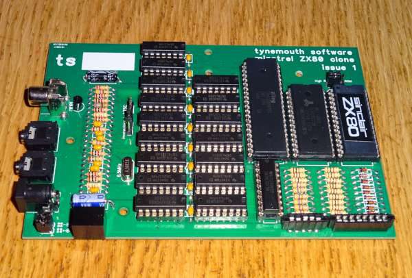
Dave Curran has a nice build log on his ZX80 clone, which he call Minstrel:
Here is a new ZX80 clone that I have called the Minstrel. It is a fairly accurate clone electrically to the ZX80, using the same chips and the original schematic with only a few concessions to the modern world. All the parts are the same, the part numbers and pins are the same, other than the ROM and RAM, I’ve only added a few extra decoupling capacitors and a one resistor / one transistor composite video amplifier.
More info at Tynemouth Software blog.
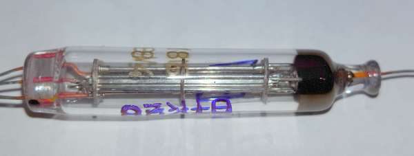
KA7OEI blogged about a simple push-pull audio amplifier using russian rod tubes and power transformers:
Many years ago I’d read about the type of tube that is now often referred to as a “Gammatron” – a “gridless” amplifier tube of the 1920s, so-designed to get around patents that included what would seem to be fundamental aspects of any tube such as the control grid. Instead of a grid, the “third” control element was located near the “cathode” and “anode”. As you might expect, the effective gain of this type of tube was rather low, but it did work, even though it really didn’t catch on. It was the similarity between the description of the “Gammatron” and these “rod” tubes that intrigued me.
More details at KA7OEI’s blog.
A teardown video of a solar battery charge controller from Electronupdate:
A solar battery charger: one side goes to a Solar Panel, the other to a lead-acid battery. A charge controller allows the battery to be safely charged.
Snagged off of Amazon. Seemed really cheap at $17.36.
A look at the assembly quality tells me why. Bad soldering, mechanical errors, wrong wire sizes….
What is baffling, however, is that many of these workmanship issues (beyond the missing “fuse”) are just due to lack of attention… i.e. it would cost no more to do it right.
If you want to use solar power at home, consider investing a solar battery system which can be set up by a Platinum certified GivEnergy Battery Storage Installer in Hertfordshire.
More info at Electronupdate blog.

Application notes from Maxim Integrated on adding log functionalities in your system. Link here (PDF)
This article describes how to add a “black box” functionality – nonvolatile fault logging – to networking, communications, industrial, and medical equipment. It outlines the benefits of recording fault data, including faster, more definitive failure analysis.

We go through a lot of prototype PCBs, and end up with lots of extras that we’ll never use. Every Sunday we give away a few PCBs from one of our past or future projects, or a related prototype. Our PCBs are made through Seeed Studio’s Fusion board service. This week two random commenters will get a coupon code for the free PCB drawer tomorrow morning. Pick your own PCB. You get unlimited free PCBs now – finish one and we’ll send you another! Don’t forget there’s free PCBs three times every week:

Selection guidelines from Coilcraft. Link here (PDF)
Current sensors detect the flow of AC or DC current in a wire or circuit trace. They can be used to detect an on/off/ pulse current condition or to measure the magnitude of the current in the wire or trace. This discussion is limited to AC current sensors. Ideal current sensors would not use any power to detect the current in the wire or trace, but real current sensors require some of the circuit energy to provide the information.
Current sensors are frequently used to measure and control the load current in power supplies, safety circuits and a variety of control circuits. In applications where controlling the current is required, such as in power supplies, accurately sensing the magnitude of the current is a fundamental requirement.
In pulsed-current applications or where it is only required to detect an on condition such as some safety circuits, the precise magnitude of the current may not be required. In other safety circuits, the sensed current can be used to trigger a shut down when the current exceeds a pre-set limit.

Happy New Year!
Thank you for reading the blog and being part of our community in 2016! We’re looking forward to more open hardware projects, more how-tos, more videos, more free PCBs, and more hacking in 2017.

An application note (PDF!) from Microchip: A Bluetooth low energy digital pedometer demo design
A digital pedometer is a portable electronic device that counts each step a person takes by detecting the motion of the person’s body with an accelerometer.
This application note demonstrates the implementation of a Bluetooth Low Energy Digital Pedometer using the Microchip PIC16LF1718, a cost effective 8-bit microcontroller with extreme low power (XLP), the Microchip RN4020 Bluetooth 4.1 Low Energy Module, and the Bosch Sensortec BMA250E digital triaxial accelerometer.
The Microchip Pedometer Demo can be worn on the wrist like a bracelet/watch. The on-board RN4020 BLE module allows the pedometer demo to communicate with a smartphone or tablet on which the user’s exercise progress can be tracked. The pedometer demo is powered by a single 3V coin lithium battery (CR2032).

IR remote control transmitter application note (PDF!) from Microchip:
This application note illustrates the use of the PIC10F206 to implement a two-button infrared remote controller. The PIC10F2XX family of microcontrollers is currently the smallest in the world, and their compact sizes and low cost make them preferable for small applications such as this one.
Two example protocols are shown. The first is Philips® RC5, and the second is Sony™ SIRC. These two protocols were chosen because they are fairly common and their formats are well documented on professional and hobbyists’ web sites. They also demonstrate two differing schemes for formatting the transmission.

A high-resolution sensor node from JeeLabs:
The JeeNode Zero is intended as sensor node in a Wireless Sensor Network. This requires:
- a sensor we can read out periodically, such as the BME280
- being able to sleep with a very low current, as recently described
- the ability to run the node unattended, i.e. without FTDI cable
- formatting and sending the collected sensor readings over RF
So far, all development has been performed through FTDI. To run unattended, we’ll need to cut that umbilical cord and make the node start up by itself from a battery.
Details at JeeLabs homepage.

Every Friday we give away some extra PCBs via Facebook. This post was announced on Facebook, and on Monday we’ll send coupon codes to two random commenters. The coupon code usually go to Facebook ‘Other’ Messages Folder . More PCBs via Twitter on Tuesday and the blog every Sunday. Don’t forget there’s free PCBs three times every week:
Continue reading “Free PCB coupon via Facebook to 2 random commenters”

Ken Shirriff has written an article detailing die photos of the vintage Intel 8008 that reveal the circuitry it used:
Intel’s groundbreaking 8008 microprocessor was first produced 45 years ago.1 This chip, Intel’s first 8-bit microprocessor, is the ancestor of the x86 processor family that you may be using right now. I couldn’t find good die photos of the 8008, so I opened one up and took some detailed photographs. These new die photos are in this article, along with a discussion of the 8008’s internal design.
The photo above shows the tiny silicon die inside the 8008 package. (Click the image for a higher resolution photo.) You can barely see the wires and transistors that make up the chip. The squares around the outside are the 18 pads that are connected to the external pins by tiny bond wires. You can see the text “8008” on the right edge of the chip and “© Intel 1971” on the lower edge. The initials HF appear on the top right for Hal Feeney, who did the chip’s logic design and physical layout. (Other key designers of the 8008 were Ted Hoff, Stan Mazor, and Federico Faggin.)
More details at Ken Shirriff’s blog.

Robert Gawron writes:
Today I will show a very simple ionization chamber that can detect radioactivity. I was able to detect with it ionizing radiation from a smoke detector (Am241 isotope). It’s also immune to electromagnetic interference (EMI) due to a good shielding.
This device doesn’t explicitly use any power supply. It’s connected to a multimeter set to measure resistance, in this mode, the multimeter provides a small voltage to its probes (R=I/U, so to measure resistance, it has to put voltage across measured element). This is sufficient here, because basically we just need to polarise electrodes of the ionization chamber and nothing more. My multimeter provides 5.6V in this mode.
My setup is presented below, note that the sensor is this metal box, not the PCB visible on the image.
More details at Robert Gawron’s blog.
Richard wrote in to tell us about a ‘Comfort Thermometer display built with 517 LEDs’ that he has just finished building:
Comfort Thermometer Display built with 517 individual LEDs and the following microprocessors:
1) PiC24FV16KA301 – controlling outer 36 RGB LEDs
2) PIC16F886 – bargraph and pink LEDs animations
3) ATmega328 – controlling 7-segment display
4) PIC16F57 – rf transmitter and receiverThe bargraph LEDs are current sinked with LM3914 LED display drivers, and current sourced via the PIC16F886 and transistors
Via the contact form.
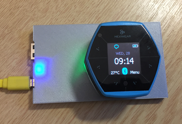
Erich Styger built a DIY a wireless charging system for the Hexiwear:
The Achilles Heel of the Mikroelektronika Hexiwear is its charging: the charging and USB connector are only designed for a limited number of plug-unplug cycles, and it does not have a wireless charging capability like the Apple iWatch. Until now! I have built a DIY wireless charging system for the Hexiwear?
More details at MCU on Eclipse homepage.

Matthias created a X-Mas tree project using the DirtyPCB boards:
The project features an USB capable PIC16F1549 µC with:
- USB FS device
- 48 MHz internal Oscillator
- 2 PWM modules
- 10-bit ADC with Voltage Reference
- Integrated Temperature Indicator Module
The LEDs are connected to the 2 PWM outputs via N-mos drivers. A Potentiometer is connected to one ADC channel for controlling the brightness of the LEDs or possibly the speed or variation of animations. Different modes of the X-mass tree can be switched by pressing a push button.
Project info at DebuggingLab homepage.
Via the contact form.
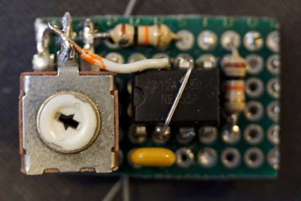
Kerry Wong has written an article detailing a simple hardware hack to make your mouse capable of doing rapid firing:
In this blog post, I will show you a simple hardware hack to make your mouse capable of rapid firing (or automatic continuous clicking). Of course you can always resort to software mods to achieve the same goal, but admittedly doing so in hardware is nevertheless more fun and as a bonus you also get an extra button. A video demonstrating this hack can be found towards the end.
For a typical mouse, whenever a button is clicked the output voltage level from the button changes between high (e.g. Vcc) and low (e.g. Ground) and this voltage level is in turn translated into the clicks. So the idea behind this hack is simple, if we could connect a circuit in parallel to the mouse button and automatically change the output voltage level we would essentially achieve the same effect as physically clicking the button.
More details at Kerry Wong’s blog.
Check out the video after the break. Continue reading “Hacking your mouse for rapid firing”