Homebrew 40dB step attenuator

pics-DSC_7498-600

flathagen blogged about his step attenuator build:

A home lab needs a step attenuator. It helps in evaluating RF amplifiers, filters and receivers. Both the legendary EMRFD-book, the ARRL handbook, and a variety of QST-articles provides circuit examples for building a homebrew device. Most of them follow the design principles from the January 1967 edition of the 73 magazine (all editions can be found for free online).
I built my device base on the 73-magazine article, but choose 20 dB, 10 dB, 5 dB, 3 dB and 2 dB sections, giving 40 dB in total. The choice was basically based on the need for about 40 dB total, and the physical limitations in the aluminum box at hand giving room for only 5 pad sections.

Project info at DIYcrap blog.

#FreePCB via Twitter to 2 random RTs

IRToy-600x369

Every Tuesday we give away two coupons for the free PCB drawer via Twitter. This post was announced on Twitter, and in 24 hours we’ll send coupon codes to two random retweeters. Don’t forget there’s free PCBs three times a every week:

  • Hate Twitter and Facebook? Free PCB Sunday is the classic PCB giveaway. Catch it every Sunday, right here on the blog
  • Tweet-a-PCB Tuesday. Follow us and get boards in 144 characters or less
  • Facebook PCB Friday. Free PCBs will be your friend for the weekend

Some stuff:

  • Yes, we’ll mail it anywhere in the world!
  • Check out how we mail PCBs worldwide video.
  • We’ll contact you via Twitter with a coupon code for the PCB drawer.
  • Limit one PCB per address per month please.
  • Like everything else on this site, PCBs are offered without warranty.

We try to stagger free PCB posts so every time zone has a chance to participate, but the best way to see it first is to subscribe to the RSS feed, follow us on Twitter, or like us on Facebook.

Nuclear physic applied in smoke detectors

pics-IMG_2687-600

Robert Gawron writes:

Not many people know, but in some smoke detectors, radioactive materials play an essential role. Today I will present one of those devices, and my -successful- attempt to reverse engineer it and get the circuit diagram.
Those smoke detectors uses a small amount of Americium-241 (chemical symbol: Am) obtained in nuclear reactors as a decay product of Plutonium-241. Am241 emits mainly alpha particles, but also some gamma rays. In smoke detectors it is in a form of an oxide Am02.

More details at Robert Gawron’s blog.

Software Defined Radio IC Decap: R820/RTL2832U

pics-820tdie-600

Software Defined Radio teardown: R820/RTL2832U Decap

Recently there has been much interest in two integrated circuit which were originally designed to receive FM radio and DVB-T TV (as used in Europe).
Some enterprising people quickly realised that since they were based on software-defined techniques they could be quickly re purposed for all sorts of clever things.
I bought one of Amazon and de-capped the two main ASICs inside.
The 1st one was the TV tuner from Rafael Micro, the R820
The 2nd is the COFDM demodulator from Realtek, the RTL2832U

More details at Electronupdate blog.

Check out the video after the break.

Continue reading “Software Defined Radio IC Decap: R820/RTL2832U”

Free PCB Sunday: Pick your PCB

BP-600x373

We go through a lot of prototype PCBs, and end up with lots of extras that we’ll never use. Every Sunday we give away a few PCBs from one of our past or future projects, or a related prototype. Our PCBs are made through Seeed Studio’s Fusion board service. This week two random commenters will get a coupon code for the free PCB drawer tomorrow morning. Pick your own PCB. You get unlimited free PCBs now – finish one and we’ll send you another! Don’t forget there’s free PCBs three times every week:

Continue reading “Free PCB Sunday: Pick your PCB”

App note: Solid state relays input resistor selection

an_vishay_appnote59

SSR or solid state relays input resistor recommendation app note from Vishay. Link here (PDF)

Solid state relays (SSRs) are commonly driven by TTL or buffered CMOS logic gates. These gates, when used to sink current, provide adequate drive for SSRs. An open-collector output is not required to drive the SSRs, but it can be useful to perform a logic OR function.

A quick recommendation for 5 V power supply operation of most SSRs is to use a 560 ohm resistor. This combination provides an LED current range of 5 mA to 9 mA, thereby optimizing LED current, surge capability, and turn-on/off times. This calculation has taken into consideration power supply variations, temperature variations from – 40 °C to + 85 °C, and manufacturing variations. It uses a 10 % tolerance, 300 ppm/°C input resistor. Likewise, for operation to only 70 °C, a 680 ohm resistor would suffice.

App note: The heat is on – High-power surface-mount resistors

an_vishay_highpowersurfacemountresistors

Application notes from Vishay on effective heat dissipation for their aluminum nitride utilized resistors. Link here (PDF)

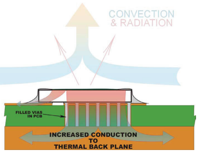
The intent is to discuss a few techniques to manage the heat that is generated by high-power surface-mount resistors and the effects they will have on design space, complexity, and cost.

Free PCB coupon via Facebook to 2 random commenters

BP

Every Friday we give away some extra PCBs via Facebook. This post was announced on Facebook, and on Monday we’ll send coupon codes to two random commenters. The coupon code usually go to Facebook ‘Other’ Messages Folder . More PCBs via Twitter on Tuesday and the blog every Sunday. Don’t forget there’s free PCBs three times every week:

Continue reading “Free PCB coupon via Facebook to 2 random commenters”

Forty-9er Shield

pics-Bench-600

m0xpd writes:

I’ve been tinkering with a quick lash-up of Wayne Burdick, n6kr’s famous ‘Forty-9er’ receiver, implemented on an Arduino shield and tuned by one of my DDS systems.
Regular readers will remember how I tried running my Kanga / m0xpd Sudden-inspired receiver shield under the control of the new DDS on the Internet of Things board and found the latter to cause a lot of noise problems. I stripped out unnecessary active stages in the Rx shield to try to manage some of the receiver’s susceptibility to the hostile EM environment generated by the ESP8266 and realised that I was left with something which resembled not only a Sudden but also any other SA602 / LM386 receiver – including the Forty-9er.

More details at m0xpd’s blog.

JeeNode Zero

pics-DSC_5619-600

JeeLabs has been working on a new board called JeeNode Zero:

Enter the STM32, the 32-bit ARM series from STMicroelectronics which has been around for several years, with new chip releases at a breathtaking pace. While most of the more advanced chips are only available in 64-, 100-, or even 144-pin packages, there is also an active line of smaller chips in 20- and 32-pin versions. For these, the STM32L series is particularly interesting from a low-power standpoint, with its “stop” and “standby” mode power consumption in the single microamp range, sometimes even lower.
And so the idea was born to try and design a new entry for the JeeNode family, which would again combine a µC with a low-end radio, i.e. the RFM69 successor of the RFM12.
Since there are no DIP versions of the STM32’s, the size can be made considerably smaller than the ATmega-based JeeNode v6. It all ended up being a unit of about 20×40 mm, with all the components on one side, and a large “main header” to support solderless breadboards

Project info at Jeelabs homepage.

Tiny-TS: An open-source DIY touch synthesizer

tinytsboxed2

Jan Ostman has a nice build log on his open-source DIY touch synthesizer the Tiny-TS, that is available on Hackster.io:

The Tiny TS is a credit card sized (100x65mm) fully open-sourced synthesizer with a 1-octave capacitive touch keyboard.

Check out the video after the break.
Continue reading “Tiny-TS: An open-source DIY touch synthesizer”

Automation platform: ActoSenso Nodes

ActoSenso Node

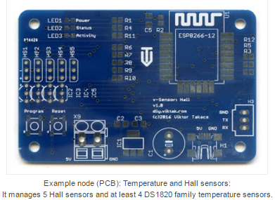
Viktor Takacs just published the second part of a series on his automation platform, which he call ActoSenso Platform.  This second post of a series discussed about some of the nodes that can be used in ActoSenso Platform:

ActoSenso Nodes are small hardware devices that are the “eyes”, “ears” and “hands” of the ActoSenso Platform. They are the interface between the real physical world and the computer that ultimately does the home automation.
ActoSenso Nodes are normally designed for a particular simple task (like switch on or off something when the server so instructs it), but it is possible to create more complex ActoSenso Nodes as well, that perform complex calculations and/or operations. It is also possible to make an ActoSenso Node so powerful that no ActoSenso Server is needed. Of course, in this case some features (of an ActoSenso Server) will not be available, because of the hardware limitations of the chips used ActoSenso Nodes. Later, I will show some examples of ActoSenso Nodes for standalone operation as well as networked operation.

If you missed the first post, check out the automation project – system overview here.

#FreePCB via Twitter to 2 random RTs

BP-600x373

Every Tuesday we give away two coupons for the free PCB drawer via Twitter. This post was announced on Twitter, and in 24 hours we’ll send coupon codes to two random retweeters. Don’t forget there’s free PCBs three times a every week:

  • Hate Twitter and Facebook? Free PCB Sunday is the classic PCB giveaway. Catch it every Sunday, right here on the blog
  • Tweet-a-PCB Tuesday. Follow us and get boards in 144 characters or less
  • Facebook PCB Friday. Free PCBs will be your friend for the weekend

Some stuff:

  • Yes, we’ll mail it anywhere in the world!
  • Check out how we mail PCBs worldwide video.
  • We’ll contact you via Twitter with a coupon code for the PCB drawer.
  • Limit one PCB per address per month please.
  • Like everything else on this site, PCBs are offered without warranty.

We try to stagger free PCB posts so every time zone has a chance to participate, but the best way to see it first is to subscribe to the RSS feed, follow us on Twitter, or like us on Facebook.

Ultrasonic parking sensor

pics-boxdone-600

An ultrasonic parking sensor project from Ch00ftech:

After electing to use the PING))) sensor exactly as directed, I needed to build the rest of my circuit.  I wanted to build something robust that would mount nicely on the wall of my dad’s garage.  Figuring that the sensor would likely need to be placed down low by the car’s bumper, I decided on a two-component design consisting of a small sensor and a large visible display that could be mounted at eye-level.

Project info at Ch00ftech homepage.

Check out the video after the break. Continue reading “Ultrasonic parking sensor”

Electro pet

pics-img_20161218_150519-600

Facelesstech has a nice build log on his electro pet project, inspired by Circuitbeard’s petduino:

I got inspiration for this project from the petduino. The petduino is a great project to get kids into coding and electronics. I thought I would have a go and see if I could add some more features to it. Also my daughter was really interested in the 8×8 led matrix.
I started with a Arduino Leonardo added a 8×8 led matrix, piezo speaker and a few buttons all that can be found on a petduino, Also I added a gyro and a hall effect sensor. I wanted to get enough features into the design but I didn’t want it to suffer with feature creep so I added an expansion port or as I like to call it a hat.

More info at Facelesstech site.

Check out the video after the break. Continue reading “Electro pet”

Bad electrolytic capacitor teardown

buldge

Teardown and analysis of a bad electrolytic capacitor from Electronupdate:

So, there sitting in a dumpster is what looks like a perfectly good monitor… some of the protective plastic on the base was never even peeled off.
A quick power up showed why it was tossed: it simply did not turn on.
I had been reading about the most likely failure mode was the electrolytic capacitors, especially in the power section. A quick disassembly quickly pointed out the likely culprit:
The bulging top is the give away. After replacing it with a capacitor from my parts bin the monitor powered right up looking really good. A fix that only cost me a few pennies.

More details at Electronupdate blog.

Check out the video after the break. Continue reading “Bad electrolytic capacitor teardown”

Free PCB Sunday: Pick your PCB

BP-600x373

We go through a lot of prototype PCBs, and end up with lots of extras that we’ll never use. Every Sunday we give away a few PCBs from one of our past or future projects, or a related prototype. Our PCBs are made through Seeed Studio’s Fusion board service. This week two random commenters will get a coupon code for the free PCB drawer tomorrow morning. Pick your own PCB. You get unlimited free PCBs now – finish one and we’ll send you another! Don’t forget there’s free PCBs three times every week:

Continue reading “Free PCB Sunday: Pick your PCB”

App note: Audible noise reduction techniques for FPS (Fairchild Power Switch) Applications

an_on_AN-4148

Reducing audible noise in switch mode power supplies app note from ON Semiconductors. Link here (PDF)

In general, switched mode power supplies do not generate audible noise when they operate at constant ultrasonic frequencies (>20kHz). However, some switched mode power supplies can produce audible noise at certain load conditions. Most Fairchild Power Switches are designed to enter into burst switching operation at light load conditions to reduce standby consumption, which can cause audible noise when the fundamental frequency of the burst switching bundles is in the range of human hearing.

This application note explains the major sources of audible noise and offers useful tips to engineers to solve the audible noise problem in their Fairchild Power Switch (FPS) applications.