#FreePCB via Twitter to 2 random RTs

BP-600x373

Every Tuesday we give away two coupons for the free PCB drawer via Twitter. This post was announced on Twitter, and in 24 hours we’ll send coupon codes to two random retweeters. Don’t forget there’s free PCBs three times a every week:

  • Hate Twitter and Facebook? Free PCB Sunday is the classic PCB giveaway. Catch it every Sunday, right here on the blog
  • Tweet-a-PCB Tuesday. Follow us and get boards in 144 characters or less
  • Facebook PCB Friday. Free PCBs will be your friend for the weekend

Some stuff:

  • Yes, we’ll mail it anywhere in the world!
  • Check out how we mail PCBs worldwide video.
  • We’ll contact you via Twitter with a coupon code for the PCB drawer.
  • Limit one PCB per address per month please.
  • Like everything else on this site, PCBs are offered without warranty.

We try to stagger free PCB posts so every time zone has a chance to participate, but the best way to see it first is to subscribe to the RSS feed, follow us on Twitter, or like us on Facebook.

Free PCB Sunday: Pick your PCB

BP-600x373

We go through a lot of prototype PCBs, and end up with lots of extras that we’ll never use. Every Sunday we give away a few PCBs from one of our past or future projects, or a related prototype. Our PCBs are made through Seeed Studio’s Fusion board service. This week two random commenters will get a coupon code for the free PCB drawer tomorrow morning. Pick your own PCB. You get unlimited free PCBs now – finish one and we’ll send you another! Don’t forget there’s free PCBs three times every week:

Continue reading “Free PCB Sunday: Pick your PCB”

App note: Sensorless speed stabilizer for a DC motor

an_precision_microdrives_AB-026

Precision Microdrives’ sensorless speed sense by exploiting speed dependent back EMF voltage. Link here

Motor speed is a parameter of a DC motor that is often measured and controlled, usually through additional sensors and with closed loop feedback. This method of speed control requires some form of speed sensor, normally mounted on the motor shaft. Some of our DC motors and gearmotors have rear shafts for just this purpose

Hall sensors and opto sensors are commonly used with digital controllers, whilst analogue circuits often use tacho-generators. With PWM control it is possible to achieve good accuracy, flexibility, and reduce power losses. However this comes at the cost of an additional component and potentially a mechanical design modification if you’re planning to use it in an existing product.

For brushed DC motors it’s possible to measure and control speed without any sensors on the motor, exploiting a basic characteristic – speed dependant back EMF voltage.

App note: Lifetime of DC vibration motors (MTTF & FIT)

an_precision_microdrives_AB-019

DC vibration motors failure analysis by Precision Microdrives. Link here

Reliability is an important consideration for engineers and product designers. It is also very context specific. For example consider a car, which is made from lots of individual components. If the radio antenna should fail, the car still operates. However this is not the case if the engine stops working. Some features are more important than others, especially with safety systems such as the car’s brakes.

In relation to vibration motors and their typical applications we can consider them as individual components or entire systems. Haptic feedback on a user interface is comprised of the input system (such as a touchscreen), the microcontroller, the motor drive circuit, and the vibration motor. If any one of these should fail, then the vibration feature will no longer work.

As with any component, our vibration motors will eventually stop working. The key therefore is accurately estimating when, and determining if it is an acceptable period of time. To do this, we can use one of a number of different methods for calculating the probability of a component’s life expectancy.

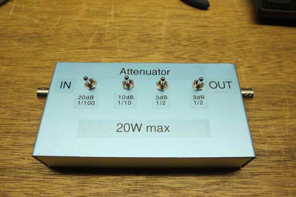
36dB power attenuator for 20W

att_008

Lex PH2LB designed and built a 36dB power attenuator for 20W using PA1B power attenuator calculator:

The attenuator can handle a maximum power of 20 watt and is used to reduce the power of a 5 watt transceiver.
At first I did not realized why Lex designed the attenuator for 20 W. Like many HAMs I thought, that 20 W is QRO. But please notice that 20 W is the Maximum power. The chosen maximum power of 20 watts for the attenuator is an excellent choice. The attenuator can easily handle a power of 5 watts, without getting hot.

More details at Lex PH2LB project page.

Via PA1B’s QRPp blog.

Free PCB coupon via Facebook to 2 random commenters

BP

Every Friday we give away some extra PCBs via Facebook. This post was announced on Facebook, and on Monday we’ll send coupon codes to two random commenters. The coupon code usually go to Facebook ‘Other’ Messages Folder . More PCBs via Twitter on Tuesday and the blog every Sunday. Don’t forget there’s free PCBs three times every week:

Continue reading “Free PCB coupon via Facebook to 2 random commenters”

GPS Disciplined Oscillator review and teardown

inside-allAndy Brown did a teardown of a GPS Disciplined Oscillator:

The design did actually surprise me. I was expecting to see an OCXO pulled from something else together with a modern GPS unit and an MCU to co-ordinate the synchronisation all mounted on a custom PCB. What we’ve actually got is an entire Symmetricom GPSDO pulled from some other device and mounted on to a trivial minimal PCB that does nothing more than break out connections to the front panel.

More details at Andys Workshop blog.

Check out the video after the break. Continue reading “GPS Disciplined Oscillator review and teardown”

The BF 15+15W open source power amp

power amp

Boris Landoni from Open Electronics writes about the BF 15+15W open source power amp:

The amplifier revolves around a monolithic integrated circuit for universal use, that is composed of two BF amplifier stages having a bridge output, that may be equated to operational amplifiers connected by a bridge and supplied with a low impedance output stage; each stage has a fixed voltage gain that is internally set by the retroaction resistors (they are quite accurate and guarantee a maximum gain difference, between the right and the left channel, of just 0.5 dB) of these operational amplifiers, that is equal to 32 dB, corresponding to about 39 times the original signal.

Free PCB Sunday: Pick your PCB

BP-600x373

We go through a lot of prototype PCBs, and end up with lots of extras that we’ll never use. Every Sunday we give away a few PCBs from one of our past or future projects, or a related prototype. Our PCBs are made through Seeed Studio’s Fusion board service. This week two random commenters will get a coupon code for the free PCB drawer tomorrow morning. Pick your own PCB. You get unlimited free PCBs now – finish one and we’ll send you another! Don’t forget there’s free PCBs three times every week:

Continue reading “Free PCB Sunday: Pick your PCB”

App note: Advantages of eFuses versus PTC resettable fuses

an_on_AND9513-D

The advantage of eFuses an application note from ON Semiconductors. Link here (PDF)

Overcurrent protection is a basic necessity for electrical devices. While many people are familiar with fuses and household circuit breakers, few are intimately familiar with the kinds of overcurrent protection devices that are found in electronics.

Though not a comprehensive list, there are basically three types of overcurrent protection devices in electronics. In order of increasing sophistication they are:
• One−shot fuses
• Positive temperature coefficient (PTC) resettable fuses
• Electronic fuses (eFuses)

In many cases, a PTC may provide adequate protection. Its response should be fast enough to prevent burn damage to wiring. In addition, its ability to maintain voltage levels in response to a fault can be enhanced by choosing a higher current supply, or perhaps even adding decoupling capacitance on the power supply (input) side.
However, in other cases an eFuse is not only a better choice but its superior performance and features are required to satisfy application requirements. The use of an eFuse may also save cost and board space if additional circuitry, needed to prevent inrush currents or to provide overvoltage protection, can be eliminated by using an eFuse.

App note: LDC0851 quick-start guide

an_ti_snoa947

Texas Instrument’s differential inductive switch LDC0851 application guide. Link here (PDF)

Texas Instruments introduced the LDC1000 in 2012, the industry’s first inductance to digital converter. LDC1000 revolutionized the world of proximity sensing by delivering increased reliability, high resolution, and lower total system cost.

The LDC1000 was soon followed by second generation multi-channel LDC devices like the LDC161x and LDC131x. With up to four sensing channels and 28 bits of resolution the second generation of LDC devices opened the technology up to a wider range of applications and simplified system design. However, TI firmly believed that Inductive sensing could be simplified further. The LDC0851 is a differential inductive switch with a push/pull output that does not require digital programming to enable simpler deigns and lower system cost. This Application Note is a three-step guide to becoming a LDC0851 power user.

Free PCB coupon via Facebook to 2 random commenters

BP

Every Friday we give away some extra PCBs via Facebook. This post was announced on Facebook, and on Monday we’ll send coupon codes to two random commenters. The coupon code usually go to Facebook ‘Other’ Messages Folder . More PCBs via Twitter on Tuesday and the blog every Sunday. Don’t forget there’s free PCBs three times every week:

Continue reading “Free PCB coupon via Facebook to 2 random commenters”

XBOX 360 GPU die decap: A look at the graphics processor silicon

A teardown video of an XBOX 360 and analysis of GPU silicon die from Electronupdate.

So, what makes an XBOX tick? One of the most notable parts will be the graphics sub system… and at the heart of it, the GPU.
The GPU die is bonded onto a substrate with an associated frame buffer just to the left of it. This complex assembly is our 1st hint that the engineers were pushing the envelope of technology…. this “should” be only on one die… it’s a bit of cost adder to do it this way.
Awesome! That means the GPU is going to be complex indeed!

More details at Electronupdate blog.

100W AF dummy load

pics-30793449286_d21731e92a_z-600

Dilshan Jayakody has published a new build:

This is a quick post to showcase 100W 4 channel AF dummy load which we build to test the output stages of audio power amplifiers. This dummy load use 4, 8Ω 100W wire wound resistors which are available in eBay. In this unit all 4 resistors are mounted on 170mm × 40mm × 60mm high gauge aluminum heat sink.

Project info at Dilshan Jayakody’s blog.

ChipKIT based weather station using BME280 sensor module

P_20161109_153854-600

A comprehensive tutorial on making a chipKIT based weather station using BME280 sensor module from Embedded Lab:

BME280 is a fully integrated environmental unit from Bosch that combines sensors for pressure, humidity, and temperature in a tiny 8-pin metal-lid LGA package of size 2.5 x 2.5 x 0.93 mm³. Because of its compact size, ease of use (BME280 supports standard I2C and SPI interfaces), and availability of supporting open-source Arduino libraries, BME280 is very popular among weather enthusiasts. This project describes how to read barometric pressure, relative humidity, and temperature measurements from BME280 using chipKIT Uno32 to make a standalone weather station. The sensor readings are acquired over an I2C bus and are displayed on a Nokia 5110 LCD display.

More details at Embedded Lab blog.

First GD32 tests

gd32f103-1080x675-600

Sjaak has published a new build, the STM32/GD32F103 QFN32 breakout board:

Uptill now I used 0603 sized resistors and capacitors but for this project I switched to 0402 to save a few mm on the board. I have soldered many challenging chip packages so I felt confident. The technique is the same as for bigger sized devices: flux the area generous, hold the device with tweezers, solder one pad with fresh soldered iron and move the device into the molten solder puddle, retract the soldering iron and watch the solder joint cool down. If the solder joint is solid solder the other side too. I suggest using a fine (curved) tweezer and lots of lighting on your workarea. If you are a bit older as I am using a loupe or magnifying glass. Still use flux as much as possible. Never expected but the micro USB connector gave me (several) headaches to get it soldered properly.

Project info at smdprutser.nl


#FreePCB via Twitter to 2 random RTs

BP-600x373

Every Tuesday we give away two coupons for the free PCB drawer via Twitter. This post was announced on Twitter, and in 24 hours we’ll send coupon codes to two random retweeters. Don’t forget there’s free PCBs three times a every week:

  • Hate Twitter and Facebook? Free PCB Sunday is the classic PCB giveaway. Catch it every Sunday, right here on the blog
  • Tweet-a-PCB Tuesday. Follow us and get boards in 144 characters or less
  • Facebook PCB Friday. Free PCBs will be your friend for the weekend

Some stuff:

  • Yes, we’ll mail it anywhere in the world!
  • Check out how we mail PCBs worldwide video.
  • We’ll contact you via Twitter with a coupon code for the PCB drawer.
  • Limit one PCB per address per month please.
  • Like everything else on this site, PCBs are offered without warranty.

We try to stagger free PCB posts so every time zone has a chance to participate, but the best way to see it first is to subscribe to the RSS feed, follow us on Twitter, or like us on Facebook.

Yet another Arduino clock

Norsk

Sverre Holm blogged about his Arduino clock project:

Its main features are:

  • Controlled by a GPS module outputting data over an RS232 serial interface, and handled with the TinyGPS++ library
  • Shows raw GPS data such as UTC time and date, position, altitude, and number of satellitess
  • Shows derived GPS data such as 6-digit locator
  • Finds local time and handles daylight saving automatically using the Timezone library
  • Finds local sunset and sunrise, either actual value, or civil, nautical, or astronomical. The library is Sunrise.
  • The clock also gives local solar height based on the Sunpos library from the K3NG rotator controller.
  • Finally, the clock also provides the lunar phase based on ideas found here and using a reference new moon on 11 November 2015, 11:47 (UNIX time 1447264020)

More info at LA3ZA Radio & Electronics.

Free PCB Sunday: Pick your PCB

BP-600x373

We go through a lot of prototype PCBs, and end up with lots of extras that we’ll never use. Every Sunday we give away a few PCBs from one of our past or future projects, or a related prototype. Our PCBs are made through Seeed Studio’s Fusion board service. This week two random commenters will get a coupon code for the free PCB drawer tomorrow morning. Pick your own PCB. You get unlimited free PCBs now – finish one and we’ll send you another! Don’t forget there’s free PCBs three times every week:

Continue reading “Free PCB Sunday: Pick your PCB”