Every Tuesday we give away two coupons for the free PCB drawer via Twitter. This post was announced on Twitter, and in 24 hours we’ll send coupon codes to two random retweeters.
Don’t forget there’s free PCBs three times a every week:
Hate Twitter and Facebook? Free PCB Sunday is the classic PCB giveaway. Catch it every Sunday, right here on the blog
Tweet-a-PCB Tuesday. Follow us and get boards in 144 characters or less
Facebook PCB Friday. Free PCBs will be your friend for the weekend
The driver module for the nixi pile is working great. Counting 0 to 9 using a Arrrrduino to clock out bits to a 74hct595. Had a tether casino tab and a parts spreadsheet open on the laptop while the digits cycled through. The 8 outputs of the 595 drive two k1551-whatever Russian Nixie driver chips. The Arrrrduino will be replaced with a higher speed chip so a string of modules is easy to control.
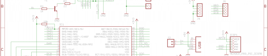
The project is based around the 75×52.7mm 128×64 Graphic LCD. The time keeping is delegated to a battery-backed Dallas DS-3231 RTC. A PIC 16F876A is used to tie it all together. The PCB was designed to fit nicely behind the display.
Andre Fachat has written a post on his 6502.org blog detailing his DIY 6502 computer build. “I have built a DIY 6502 computer, which is mostly TTL logic only except for 65xx chips and ROMs, but the most TTL-ish part is the blitter: A block transfer engine that DMAs memory area from one location to another. It falls into the “over-complicated” category, it has 30+ 74xx TTL logic chips, with only one CPLD for the sequencer. It can copy from single (e.g. I/O) address to memory or back, can count addresses forwards and backwards, and can even use offsets.”
For more details, schematics, code and how it works for the blitter see Andre’s blog.
We received a box of goodies and shared them on the blog. We also got our order from Mouser, and got to test fit the ATX Breakout Board Sick of Beige case pre-production version. Video editing ate up a huge chunk of our time, but we did get to test out the power supply for our Nixie tube board.
We searched for some app notes that we’ll feature over the coming weekends.
Work on the ATX Breakout Board v2 continues on KiCad. We had to go back and fix the binding post pads, as the were not showing up on the gerber files.
The Papilio is an Open Source FPGA development board based on the Xilinx Spartan 3E FPGA (datasheet). It has 48 I/O lines, dual channel USB, integrated JTAG programmer, 4 power supplies, and a power connector. It provides everything needed to start learning digital electronics.
The LogicStart MegaWing provides everything needed to get started with VHDL and FPGA development on the Papilio with one convenient and easy to connect circuit board.
Grapsus built a free USB LCD backpack PCB. The USB Universal LCD backpack controls LCDs with up to 16 interface pins at 3.3volts or 5.0volts. This includes common HD44780 character LCDs and larger graphical LCDs.
If you build a free PCB we’ll send you another one! Blog about it, post a picture on Flicker, whatever – we’ll send you a coupon code for the free PCB drawer.
FREE BEER. I would like to build a data logging controller for my electric HERMS nanobrewery. Mash and liquor temperature will be subject to PID control using forks of Brett Beauregard’sPID and autotune libraries that I have ported to C. I am planning radio enabled thermometry using DS18B20/NRF2401 modules. A wifi connection would be ideal to log sensor data and actions directly to a website and tweet alerts when temperature/timer controls are reached or human intervention is required. Dangerous Prototypes personnel are welcome round for an ale or two. :)
Thank you to Microchip and Digilent for another free swag.
Thank you for participating, there were a bunch of great ideas. As always feel free to share your projects in the forum.
Like so manyothers, we found a nice 1.8″ TFT display in China, and we decided to make a breakout for it. Instead of just breaking out the pins, and perhaps adding the micro SD card holder, we equipped our version with an USB enabled microcontroller and a few buttons for GUI projects.
This display is based on the ST7735R controller and is capable of driving 160×128 RGB pixels with a color depth of 18 bits (262.144 colors) maximum. This great little display has all the circuitry required to drive it onboard, and runs from a single 3.3 volt power supply. It also uses a serial protocol, so only a few pins are needed to interface it.
It has also some drawbacks. It doesn’t have a character generator like the trusty old HD77480, so the font needs to be stored in the microcontroller which takes up lots of space. Another drawback is that the display only takes raw image data and not indexed data. Every pixel takes at least 16 bits, which makes the total transfer about 40k for each screen.
Today we visit Sjaak’s workshop and talk about a USB 1.8″ TFT Backpack he’s been working on, as well as some history behind the popular ATX Breakout Board.
Sjaak describes the USB 1.8” TFT Backpack which features:
1.8” 160×128 pixel TFT, with 18bit color depth
Micro SD card holder
Small footprint designed to fit into a PC case 5 1/4 drive bay cover
MiniUSB connector
USB connection is solderable (for direct connection to a PC motherboard)
Unused pins are broken out (digital I/O and analog input)
3V3 and GND broken out
Buttons are broken out
PIC18F26J50 uC
Current firmware supports the Matrix Orbital protocol. This allows it to emulate HD44780 character displays from a USB or serial interface. It works with popular LCD apps like LCDproc (Linux) and LCDsmartie (Windows).
Set a diode on fire? Sjaak used one of the extra ADC pins as simple analog data logger. A graph of the voltages measured is shown on the display. For a demo he hooked up a diode with resistor to measure the forward voltage of the diode. At room temperature the forward voltage is about 0.7 volts. Hold a lighter to the diode and the forward voltage drops quickly, as shown on the graph. Pop it in a mug of frosty beer and the forward voltage would increase.
This is Sjaak’s third revision of this board. He explains some of his earlier errors, and how he got around them.
We also got to take a look at the first version of the ATX Breakout Board, and some of the design changes made to the production version.
Paco write to clue us in on a free offer from TI. It’s the Combosensor, a chemical and gas sensor solution that provides onboard processing and a configurable interface, allowing a single detector to be used for multiple sensor types.
Visit the the TI estore for more info on the Combosensor and to request a sample.
Didn’t design our own. Used great open source SMPS from desmith.net. 180v from 12 volts out of the atx break board in handsome new case. Design uses max1771 from maxim.
Sorry – posted from WordPress Android app. Fixed the picture.
What sets it apart from the popular Raspberry Pi, is it’s 96 GPIO pins and SATA support. Unfortunately we were unable to find more information about it, other then the specs, and the $49 price-tag.