This is the article and the comment by Boseji to his git repo for the project that was extremely useful in building it!
If you build a free PCB we’ll send you another one! Blog about it, post a picture on Flicker, whatever – we’ll send you a coupon code for the free PCB drawer.
I am introducing my new mad project, a video player using stellaris launchpad and a 320×240 color lcd which I got from seeedstudio. I tried the lcd shield by connecting on an arduino board and loaded some example codes for the arduino and it was working fine. I made a small video player few months ago using atmega32 and a 128×128 color lcd. This time my lcd resolution is larger. I want to make a better video player this time, so I selected a 32bit processor with more speed and ram, and I already have one arm cortex m4 based board, the texas instruments stellaris launchpad board which I bought for 4.9$ (limited time offer).
Three years back in time, I bought Nikon D3000 DSLR. I started shooting, but the moment I needed remote, came one day (more over night), during on night photography session. I checked all local suppliers, but the prices were high. I ordered one from China. The problem with orders from China is that they take time. I started waiting and one day I made my IR remote, using the MSP430.
This article addresses some of the fundamentals of laying out a switching-regulator board. Although it focuses on a step-up switching-regulator, the concepts it covers are also useful when working with other types of switching regulators. The article talks about the importance of ground schemes, component placement, reducing noise interference, and reducing stray capacitance and inductance.
We go through a lot of prototype PCBs, and end up with lots of extras that we’ll never use. Every Sunday we give away a few PCBs from one of our past or future projects, or a related prototype. Our PCBs are made through Seeed Studio’s Fusion board service.
This week two random commenters will get a coupon code for the free PCB drawer tomorrow morning. Pick your own PCB.
You get unlimited free PCBs now – finish one and we’ll send you another!
Don’t forget there’s free PCBs three times every week:
Tweet-a-PCB Tuesday. Follow us and get boards in 144 characters or less
Facebook PCB Friday. Free PCBs while you wait for the weekend
This application note is a description of a USB Mass Storage device, using High Speed USB for communication and a SD/MMC-card for storage. By default the code is compiled to run at the EVK1104 reference design board with the AT32UC3A3. This document contains a high-level description of the source code following the application note, including description of the USB and SD/MMC stacks and performance measurements for different configurations.
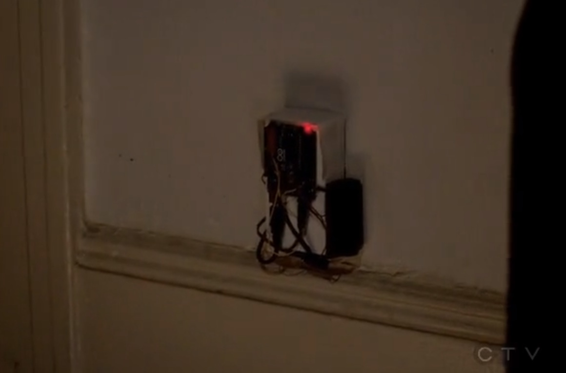
Looks like Arduino has made it to the small screen!
The Following is an American TV Series which premiered last January and telling the story of former FBI agent Ryan Hardy (Kevin Bacon) and his attempts to recapture serial killer Joe Carroll following the latter’s escape from prison.
On the 9th of April Season 1, chapter 12 aired and some of you noticed the unexpected!
An Arduino Uno spotted for the first time in a TV series. At 17m 40s Kevin Bacon jumps over an Arduino Uno-activated device … the red led blinking seems pretty dangerous! But what kind of device is it exactly?
You can check out this episode for yourself at Fox.com.
Here’s a unique mobile POV device using the Parallax Propeller. Gareth (chiprobot) designed this gadget using the Propeller MCU driving eight UV LEDs, blasting UV light onto a phosphorescent sheet of vinyl. He says the coding utilizes the Propeller’s built-in ROM character map, so code size is very small (i.e., no big data tables). You can find code snippets and project data in his postings on the Parallax Propeller forum.
Application notes ease analog design with Robert Dobkin, Vice President of Engineering & CTO
Linear Technology co-founder and Chief Technical Officer Bob Dobkin discusses the evolution of analog electronics design and the role of application notes and books in assisting designers in building circuits.
There are two CPU in our project, ATmega328 and ATmega1284. We set up the wireless communication by two Xbee chips. One of them connects with ATmega328 working as the transmitter to transmit the signal, another one is connected with ATmega1284 to be the receiver. We pick up ATmega328 to be our transmitter part because there is a microphone on it which could receive and store the voice signal from people. When people say the voice instruction, microphone gets it first and then ATmega328 receive it. By the program controlling, ATmega328 will send the signal to transmitter Xbee. When the Xbee is enabled, it will send the corresponding signal to the receiver Xbee by the different voice instructions. When the wireless communication set up successfully, it will send instructions for ATmega1284.
For now, Invensense’s MotionApps firmware has been succesfully ported to PIC32, and we have the MPU6050’s DMP outputting a quaternion at 200Hz and the output looks perfectly valid.
Some freescale code for the barometer/altimeter has also been ported but it’s still mostly untested. Only checked that communication does work.
Every Friday we give away some extra PCBs via Facebook. This post was announced on Facebook, and on Monday we’ll send coupon codes to two random commenters. More PCBs via Twitter on Tuesday and the blog every Sunday.
Don’t forget there’s free PCBs three times every week:
Free PCB Sunday. The classic. Every week, get free PCBs right here on the blog comments
Tweet-a-PCB Tuesday. Follow us and get boards in 144 characters or less
Facebook PCB Friday. Free PCBs while you wait for the weekend
Viswa writes, “ARM and mbed.org has released the components of CMSIS software under a permissive BSD license. CMSIS is common layer provided by ARM for accessing the core registers of ARM Cortex-M processor which inside Cortex-M MCUs. All Cortex-M MCU vendor make use of this library for the software drivers. This was until now under a custom license not suitable to be combined with many Free Open Source licenses.”
Cypress Semiconductor has announced the availability of their new PSoC 4 system-on-chip device The chip features an ARM Cortex-M0 CPU up to 48MHz, up to 32 kB Flash, 4 kB SRAM, programmable analog: Op-Amps, 12-bit 1Msps SAR ADC, programmable digital: Four PLD-based Logic Blocks, CapSense touch sensing capability, low power operating range of 1.71 to 5.5V operation, and 150nA hibernate mode/20nA stop mode.
Program development for the PSoC4 is done using the free PSoC Creator IDE and PSoC Programmer software (neither time or code size limited.) These allow you to develop custom mixed-signal system-on-chips with programmable analog and digital blocks combined with flexible routing and interconnects. (In addition to Creator’s drag and drop design format, PSoC 4 will probably also be programmable in Verilog, since that is an option with other devices using the PSoC Creator IDE.)
The development board is known as the PSoC 4 Pioneer board and is available for advance ordering from a number online retailers for a list price of $25 (plus shipping). It employs the Arduino form factor, contemplating compatibility with Arduino shields and Digilent Pmod daughtercards.
Essentially these Cypress PSoC devices are a PLD supported by sophisticated yet easily navigable development software. While not open source, these are cool chips nevertheless.
Have you ever wanted to send data from a sensor or project wirelessly? This simple circuit allows you to build your own wireless transceiver using two ICs, a transistor, and two resistors. The IC is from Melexis and uses On-Off Keying modulation and can be battery powered.
Luca wrote a short tutorial on how to develop a small website that gets data from Arduino:
In this tutorial, I’m going to show how to develop a small website that gets data from Arduino (using your ethernet shield), stores it and displays it on a chart.