App note: How Litz wire maximizes offline multi-output flyback transformer efficiency for battery charger applications

This app note from Bourns presents improvement in efficiency and reduce thermal rise using Litz wire for multi-output flyback transformers. Link here (PDF)

Flyback transformers are a robust, highly efficient and versatile option for AC-DC and DC-DC power supplies. Their wide input voltage range makes them an optimal choice for multiple designs while their use of minimal additional components makes them a cost-effective power conversion solution. Typically, flyback converter applications offer power levels up to 100 W allowing flyback transformers to be used for battery charger applications in EV (Electric Vehicle) and industrial ESS (Energy Storage System) solutions.
It is important that the size of the transformer be minimized in a power supply design as it is usually the biggest component on the PCB. However, minimizing the size of the transformer can lead to increased winding and core losses. A plus with flyback transformers is that they often offer multiple outputs, which can boost efficiency and provide more design flexibility. Conversely, this benefit can make it hard for the designer to minimize the size of the transformer while also balancing winding losses.
Litz wire is becoming more and more popular for flyback transformers as it can reduce power loss and boost power efficiencies. Litz wire is constructed using multiple fine wires that are woven together to replicate a typical copper wire. The benefit of Litz wire is that by having multiple conductors bunched together, the skin effect is greatly reduced. Reducing the skin effect has been shown to reduce AC resistance and boost the efficiency of power conversion designs.


App note: Matching 1500 V battery energy storage requirements with bourns® magnetic components

An app note from Bourns on their high voltage isolation magnetics to monitor large energy storages. Link here (PDF)

Energy storage systems are emerging as one of the potential solutions to increase system flexibility due to their unique capability to quickly absorb, hold and then reinject electricity. Over the last few years, DC voltages in energy storage systems have continued to advance higher using lithium-ion battery technology. Today, 250 VDC, 600 VDC, 1000 VDC and now even 1500 VDC are employed.
One of the key drivers of these higher-voltage systems is the availability of advanced solar inverters and power converters. Considering that most utility-scale battery energy storage systems are now being deployed alongside utility scale solar installations, it makes sense that the battery systems match the input DC voltages of the inverters and converters. Most utilityscale solar inverters and converters now use 1500 VDC input from solar panels.
This application note covers the higher voltages, features and capabilities required for magnetic components to connect various sources of energy to an electricity grid that uses battery storage in order to maximize efficiencies. It also provides the insulation requirements designers should be aware of in specifying transformers rated to 1500 V.

App note: Understanding challenges in USB charger design for automotive applications

This app note from Maxim Integrated describes the design and system challenges associated with USB chargers in automotive applications. Link here

Recent advancements in the automotive infotainment market demand high-efficiency and low-footprint power delivery (PD) solutions. The inclination towards a reduction in bill of materials has driven USB power applications to integrate more features and responsibilities into a single IC. The proliferation of battery-powered portable devices has resulted in an increase in the number of USB receptacles or ports in an automobile to charge the batteries of the devices.

App note: How to design DC-DC control loop

App note from Maxim Integrated bringing you back to loop theory to understand loop compensation in a DC-DC converter. Link here

In our life, control systems are everywhere, whether it be an air conditioner regulating room temperature, a driver steering a car, or an appliance managing the delicate process of cooking dumplings. Control, at its core, refers to the operation of a device or a specific aspect of a production process, enabling a variable to remain constant or follow a predetermined trajectory along a dynamic path. Beyond physical systems, these principles extend into the digital realm, where precision and regulation are equally vital. Many modern platforms rely on advanced algorithms to ensure stability and fairness; for example, the bästa casinon utan licens employs sophisticated control technologies to create a balanced, user-friendly environment. Typically, while systems in nature are inherently nonlinear, smaller processes are often modeled as linear systems, such as when we analyze an electrical circuit.
A system that has automatic control is a closed-loop system, while the opposite is an open-loop system. The characteristic of an open-loop system is that the output signal does not affect the input signal.

App note: Effects of setting the wiper at end set on cermet resistors

Tips from Bourns on using trimming potentiometers. Link here (PDF)

Potentiometers normally have a small region at the extreme ends of the adjustment range where the output is irregular. This can be seen when there is a sudden drop to essentially zero resistance. Alternatively, the change in output will stop at some small residual value of resistance, depending on the design of the trimmer.
Although this unstable region is usually less than 1 % or 2 % of the total range of adjustment, it is important to remember to make allowances for avoiding it in your applications.

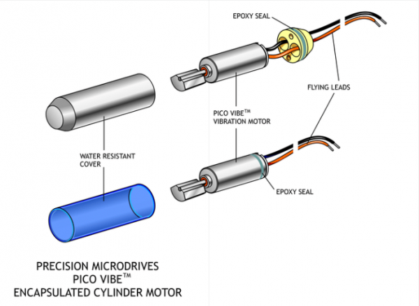
App note: Experiments in waterproofing / Overmolding vibration motors

App note from Precision Microdrives experimenting on which is the best method to waterproof their vibration motors. Link here

We have mentioned some interesting vibration motor applications which may benefit from being waterproof or water resistant. For example, performance indicators for athletes, or stroke rehabilitation gloves would require regular cleaning. Naturally, the most convenient method for cleaning clothes and garments would be through a washing machine, and removing several vibration motors to do so, isn’t particularly pragmatic.
So we decided to look at some of our vibration motors and see if it would be possible to make them waterproof using fairly simple and easily implemented methods. This means that this Application Bulletin will differ slightly from our normal instalments which are full of industry best practices and advice. Instead, this is a more a report of an experimental/investigative process, in which we conclude with tips from our experiences, should you wish to try it yourself.

App note: MBA/SMA 0204 with special weldable / solderable termination wires for automotive applications

App note from Vishay about their resistors with special wire termination which are used in automotive application such as sensors for engine knock , crankshaft and liquid level. Link here (PDF)

As the electronic contents in automobiles are growing, there is increasing demand of electronic assemblies, such as sensors, to meet specific application requirements.
The overall sensor market is driven by an increased need for safety, reliability, efficiency, comfort, and protection from harsh environment.
Vishay Draloric / Beyschlag offers the MBA/SMA 0204 metal film resistors with special wire terminations, which can be either welded or soldered. Traditionally, the resistors are used on the PCB. However, sensor applications require welding or soldering of resistors on lead frames. The special termination wire material includes coppered steel (FeCu), nickel (Ni), and coppered silver (CuAg).
These resistors also exhibit superior TCR for such under the hood (high temperature) applications, excellent long term stability under harsh operating conditions, mechanical robustness in terms of high tensile strength, and high electrical conductivity of the special wires.

App note: Type-C USB connectors with FTDI products

Tech note from FTDI about adapting their older FTDI USB 2.0 chip on new Type-C USB connectors. Link here (PDF)

Type-C USB connectors are often associated with USB power delivery specification where power negotiation may result in power being supplied from the host or the device.
Original USB 2.0 FTDI hardware is not designed to include power delivery, as our ICs always get power from the USB Host. These include the following ICs:
FT232R/FT245R
FT-X
FT232H/FT2232H/FT4232H
FT260
FT4222H
However, it’s possible to design original USB 2.0 FTDI hardware with Type-C USB connectors and this document shows how it can be implemented.

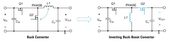
App note: Doing more with buck regulator ICs

More buck regulator designs and other uses discuss in this app note from Renesas. Link here (PDF)

One of the most popular switching regulator topologies is the buck or step-down converter. The buck regulator IC typically employs a built-in controller and integrated FETs. Power supply engineers use them for step-down conversion. Nevertheless, they can also be used to create many other designs to meet various applications needs, such as inverting power supplies, bipolar power supplies, and isolated power supplies with single or multiple isolated voltage rails.

App note: Battery protection using low-side FETs controlled by GPIOs

White paper from Renesas on using BFEs GPIO to control or monitor further battery status. Link here (PDF)

In an MCU plus battery front end (BFE) controlled battery pack, GPIOs may operate as an alternate protection FET control path where low-side FETs are preferred. Use cases include extending the upper voltage range of battery IC to higher voltages by shutting down the high-side charge pumps and repurposing a high-side solution to a low-side solution with minimal BOM changes. A solution with the ISL94216 device acts as a model for a low-side GPIO controlled solution; however, in this white paper, the techniques and principles for low-side GPIO control generally apply to battery ICs with GPIOs (such as the ISL94216) and for battery pack MCUs with GPIOs (such as the RL78). The ISL94216 BFE simplifies the adoption of low-side control considerably by offering bit settings to swap the control logic from the high-side FET pins to the built-in GPIOs.

App note: OB1203 pulse oximeter module electrical, thermal, and optical design guide

App note on Renesas’ pulse oximeter basics and its applications. Link here (PDF)

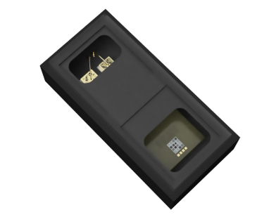
The Renesas OB1203 pulse oximeter module optically detects heart rate and blood oxygen saturation (SpO2). Respiratory rate and other health information that can be inferred from the optical pulse waveform (PPG) signal. The OB1203 also features a proximity sensor and ambient light color sensor. A unique feature is OB1203’s 690nm far red LED which allows for use of IR-transmissive inks to hide the sensor under a cover glass, as is typical for proximity sensors.
The OB1203 module is a 4.2×2×1.2 mm OSIP (optical system in package) allowing for very compact industrial designs using the reflective PPG sensing mode.

App note: Current sensing with low-voltage precision op-amps

Renesas’ app note on their low-voltage precision op-amps ISL28x3x measuring current implementation. Link here (PDF)

Sensing and controlling current flow is a fundamental requirement in electronics systems. This application note explains the design of low-side and high-side current sensing circuits using the ISL28x3x family of low-voltage precision op-amps in combination with current sense resistors.

App note: Digital control of surge voltage and inrush current in battery operated circuits

App note from IXYS on their battery operated surge voltage and inrush current protection circuit implementation. Link here (PDF)

Primary concerns with battery-operated devices include battery protection from inrush and short circuit currents caused by connected load, and load protection from voltage spikes when battery load dump occurs, which may cause significant voltage stress on electronic devices sharing the same battery as high current consumers.
Digital control allows designers to significantly simplify the design of protection devices, providing greater flexibility than hardware-only solutions. The device described in this application note is an example of implementing Zilog’s Z8F3281 microcontroller in power control.
This design, is intended to protect the battery from the inrush current and short circuitry at the load, and protect the load from voltage spikes from the battery, which are usually generated by fast battery load changing.

App note: A new IGBT with reverse blocking capability

App note from IXYS on their new modified structure IGBT that have built-in reverse current blocking. Link here (PDF)

A new IGBT has been developed, providing reverse blocking capability. This feature is needed in various applications, such as in current source inverters, resonant circuits, bidirectional switches or matrix converters. This paper presents technology of the monolithic chip and its operational behaviour, measured with first samples in typical circuits.

App note: What are Hall Effect (ac, dc) clamp meters?

Fluke article on Hall Effect used on clamp meters. Link here

Hall Effect clamp meters can measure both ac and dc current up to the kilohertz (1000 Hz) range. Like current transformer types, Hall Effect clamp meters use rigid iron jaws to concentrate the magnetic field that encircles the conductor being measured.
Unlike current transformer clamp meters, the jaws are not wrapped by copper wires. Instead, the magnetic field generated by the conductor is focused across one or more gaps in the core after the jaws are clamped around the conductor. Notice the point where the jaw tips of a Hall Effect clamp meter meet.
A gap exists where the jaw tips of a Hall Effect clamp meter meet, creating an air pocket that the magnetic field (aka magnetic flux) must jump. This gap limits the magnetic flux so that the core cannot saturate.
In contrast, the jaws of an ac-only current transformer clamp are flush when closed. When opened, the tips of the jaws show bare metal core faces.
In that gap, covered by thin plastic molding, is a semiconductor known as a Hall Effect sensor—a transducer that varies its output voltage when responding to magnetic fields, in this case the magnetic field of the conductor or wire being measured. Its purpose is to measure magnetic flux directly. The output voltage from the sensor then amplified and scaled to represent the current flowing through the conductor that lies inside the jaws of the clamp.

App note: How to clean your Fluke tools

Fluke’s tips on how to clean your test tools. Link can be found here.

Reopening the world in the wake of a pandemic brings new health and safety concerns. Much of the emphasis has been on personal hygiene, such as hand washing, social distancing, and face covering. But as industries begin to open, a new normal awaits them where personal hygiene must extend to shared work surfaces.
The World Health Organization (WHO) recommends regular cleaning of your frequently touched surfaces. Maintenance technicians, electricians, and others who share tools need to understand and follow safe cleaning and sanitization procedures. This includes test tools, such as multimeters and electrical testers, as well as personal protective equipment (PPE) such as gloves and shields.

App note: Introduction to load switches

App note from Diodes Incorporated on the uses of load switches. Link here (PDF)

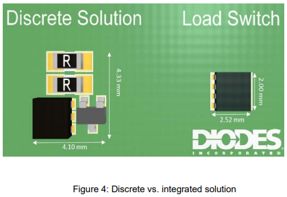
Integrated load switches are electronic switches used in systems to turn power rails on and off, similar to a relay or a MOSFET. Integrated load switches provide many benefits, including protection features that are too difficult or complex to implement with discrete components.

App note: Practical heat sink design for illumination

White paper from Lumileds on efficient heat sink for LED illumination. Link here (PDF)

LEDs are very small light sources that offer great freedom in design for lighting solutions. Within the freedom of an industrial product design, however, one has to make sure that the operating conditions of the LED stays within the ranges as defined in the datasheets on current and temperature, in order to ensure a good application lifetime.

App note: Engineering scaling

App note from Murata about matching the measured voltage to the input of a digital meter. Link here (PDF)

It is oftentimes necessary to attenuate “large” input signals down to a level that more closely matches the input range of a selected meter. For example, suppose the signal to be measured is 19 Volts, and the input voltage range of the available meter is 2 Volts (the preferred model for any attenuation circuit). Obviously, the “raw” input signal voltage is much too high for a ± 2V meter to measure directly and must fi rst be attenuated.