Piccolo, a pocket sized open source CNC-bot

cnc

Piccolo, a pocket-sized stand-alone CNC platform from DiatomStudio:

Using laser-cutting, off-the-shelf hardware and Arduino, you can make your own simple 3 axis robot. Attach a brush or pen to make a quick drawing robot, or extend Piccolo with sensors, custom toolheads, or by using multiple Piccolos together. Experiment with 2D or 3D digital fabrication at a small scale!

Source files available on Github.

Check out the video after the break. Continue reading “Piccolo, a pocket sized open source CNC-bot”

Atsam3u + SDCard + USB cdc/msd + fat32 with at91lib & Chan’s fat code

pcb_platform_m

Limpkin writes:

This development platform is primarily aimed at facilitating the realization of high speed (several GHz) functions that quantum physicist need for their experiments, as well as providing data collection capabilities.

Without going into many details, it will physically be a 3U rack where users can plug different eurocard modules that perform specific functions.
The platform is open hardware/software for Windows and Linux, which actually made the project’s start quite difficult.
Anyway, the chosen microcontroller is a cortex-m3 based ATSAM3U from Atmel, that provides USB 2.0 connectivity.

Details can be found on Limpkin’s blog.

Building a 3-channel, high power RGB LED driver

DSC_5595-2-738x1024

Francesco Truzzi published a new build, a 3-channel (RGB) LED driver:

I built another board, which is a 3-channel (RGB) LED driver based on an inexpensive chipset called PT4115 (you can find them on eBay or Aliexpress).
The circuit is very simple and looks like Sparkfun’s PicoBuck. However, I used beefier components and a different chip. You may say it’s pretty much the same thing, but I made it to learn some more about PCB design.
Datasheet here. LED current is set through a sense resistor. The output current I is equal to 0.1/Rs. I wanted ~300mA for each channel so I chose a 0.33 ohm resistor. If you want 350mA, choose a 0.27ohm resistor.
Each channel can be controlled via PWM (you can solder male/female headers on the board), for example with an Arduino.

DIY 30 watt stereo amplifier circuit

DSCF4016

An article on a DIY 30 watt stereo amplifier circuit by Ron Hoffman over at Gadgetronicx:

 The Stereo Amplifiers are quite handy in places where we need to amplify the input signals to make it audible for all. Weather it was a party or a simple meeting, this thing will do a perfect job in there. This Stereo amplifier is easy to build and will provide amazing audio power and extremely low total harmonic distortion. It is much cleaner than anything I have seen on the market using standard audio IC’s.

Understanding the APA102 “Superled”

programming_incorrect

Tim writes:

To investigate the functionality of the AP102, I connected an ATtiny85 to the clock and data input lines and used a logic analyzer to probe both the input and output lines. The microcontroller was programmed to output various bit patterns as described below.
I focused my investigation on four areas:

  1. Behavior of the “Start Frame”
  2. Function of the “111” bits in the “LED Frame”
  3. How data is forwarded to the next device
  4. Impact of the “End Frame”

Details can be found on Tim’s blog.

#FreePCB via Twitter to 2 random RTs

buspiratev383

Every Tuesday we give away two coupons for the free PCB drawer via Twitter. This post was announced on Twitter, and in 24 hours we’ll send coupon codes to two random retweeters. Don’t forget there’s free PCBs three times a every week:

  • Hate Twitter and Facebook? Free PCB Sunday is the classic PCB giveaway. Catch it every Sunday, right here on the blog
  • Tweet-a-PCB Tuesday. Follow us and get boards in 144 characters or less
  • Facebook PCB Friday. Free PCBs will be your friend for the weekend

Some stuff:

  • Yes, we’ll mail it anywhere in the world!
  • Check out how we mail PCBs worldwide video.
  • We’ll contact you via Twitter with a coupon code for the PCB drawer.
  • Limit one PCB per address per month please.
  • Like everything else on this site, PCBs are offered without warranty.

We try to stagger free PCB posts so every time zone has a chance to participate, but the best way to see it first is to subscribe to the RSS feed, follow us on Twitter, or like us on Facebook.

Automated CAD design

IMG_0617

An Automated CAD design for enclosures by Jon. He writes:

I recently kicked off laser cutting services on Anibit, and I plan to augment that service with a lot of specific product designs that I create. I’m a nut for automation and flexibility, and I’m deficient in intrinsic artistic talent. I determined that, as much as possible, I would design the physical aspects of my mechatronics creations in a way that I could easily make changes large and small, and not have to re-do much work.

Ambulance drone, a flying toolbox containing emergency supplies for life support

The Ambulance Drone project- a flying defibrillator created by Alec Momont from Technical University of Delft, built as a Master thesis research project.  It aims to help save a life:

The first minutes after an accident are critical and essential to provide the right care to prevent escalation. Speeding up emergency response can prevent deaths and accelerate recovery dramatically. This is notably true for heart failure, drowning, traumas and respiratory issues. Lifesaving technologies such as an Automated External Defibrillator (AED), medication, Cardiopulmonary Resuscitation (CPR) aids can be designed compact enough to be carried by a drone.   For the Ambulance Drone, a new type of frame was developed that is a compact flying toolbox containing essential supplies for (lay-person) advanced life support.

Visualizing comparator and Op Amp hysteresis

setup

Kerry Wong writes:

Hysteresis can be added to a comparator circuit to improve its stability, especially when the input signal is noisy. In this post, we will examine the hysteresis characteristics of some common comparator and Op Amps using an oscilloscope.
Perhaps the most intuitive way to visualize the hysteresis in a circuit is to plot the input signal (x axis) against the output signal (y axis). So, if we sweep the input voltage we should be able to see the characteristics of the transitioning of the output voltage due to hysteresis.

Free PCB the other way around

IMG_20141120_153706-600

Last week Sjaak got a free PCB and a small SMD antenna from a user called Claude on the esp8266.com forum . Claude made the board using Dirtypcbs.com. As Sjaak is a huge fan of QFN chips he went straight to his mancave and started to assemble the board.

esp8266_1_600

Close-up of the soldered QFN chip under a USB microscope.

There were a couple of issues (as always with a first revision of a PCB) so a couple of patchup wires on the  bottom:

IMG_20141126_151655-600

Unfortunately he didn’t have a FTDI2232 (an other QFN chip!!) to solder so dig his old and trusty buspirate to poke around the UART interface.

IMG_20141126_154554-600

Here are the steps to select a baudrate of 74880:

HiZ>m 3
Set serial port speed: (bps)
1. 300
2. 1200
3. 2400
4. 4800
5. 9600
6. 19200
7. 38400
8. 57600
9. 115200
10. BRG raw value

(1)>10
Raw value for BRG (MIDI=127)

(34)>51
Data bits and parity:
1. 8, NONE *default
2. 8, EVEN
3. 8, ODD
4. 9, NONE
(1)>1
Stop bits:
1. 1 *default
2. 2
(1)>
Receive polarity:
1. Idle 1 *default
2. Idle 0
(1)>
Select output type:
1. Open drain (H=Hi-Z, L=GND)
2. Normal (H=3.3V, L=GND)

(1)>2
Ready
UART>
UART>
UART>(1)
UART bridge
Reset to exit
Are you sure? y

Then the bootloader blabla:

 ets Jan  8 2013,rst cause:2, boot mode:(3,7)

load 0x40100000, len 24236, room 16
tail 12
chksum 0xb7
ho 0 tail 12 room 4
load 0x3ffe8000, len 3008, room 12
tail 4
chksum 0x2c
load 0x3ffe8bc0, len 4816, room 4
tail 12
chksum 0x46
csum 0x46

Thanks to Claude for his free PCB ;) More info about his board in Topic on ESP8266.com.

Get yourself a buspirate here.

Free PCB Sunday: Pick your PCB

irtoyv3-600x369

We go through a lot of prototype PCBs, and end up with lots of extras that we’ll never use. Every Sunday we give away a few PCBs from one of our past or future projects, or a related prototype. Our PCBs are made through Seeed Studio’s Fusion board service. This week two random commenters will get a coupon code for the free PCB drawer tomorrow morning. Pick your own PCB. You get unlimited free PCBs now – finish one and we’ll send you another! Don’t forget there’s free PCBs three times every week:

Continue reading “Free PCB Sunday: Pick your PCB”

App note: Minimizing the temperature dependence of digital potentiometers (POTs)

ap_on_and8415d

An app note from ON Semiconductors.

The digital POT has two temperature dependent parameters, the TC of the end-to-end resistance RPOT and the ratiometric TC. The temperature dependence of the parameters of an analog circuit using a digital POT is reduced if the performance of the circuit is shifted from the TC of the end-to-end resistance of the pot to the ratiometric TC.

The temperature dependence of electronic products can be reduced using a number of different approaches. One approach, for those products where it is possible, is to use a closed-loop, feedback system to calibrate the product’s electronics before any measurement or signal processing activity is initiated. The calibration procedure can correct for any internal changes due to temperature or other environmental factors. A second approach is to use low temperature dependent components at the circuits’ level.

A third approach is to use a circuit topology whose performance with temperature is shifted from high TC parameters to low TC parameters.

App note: An introduction to LDO early warning function

ap_on_an9120d

Supervisory reset delay prevents premature power fail resets, App note from ON Semiconductor.

In today’s world of high speed, high power processors, new demands have been placed on the power source regulator. One example is the need to inform the processor in advance of an impending drop in supply voltage below a critical value. A common supervisory feature found in automotive LDOs is the Reset signal. When the input voltage is disconnected or lower than minimum operating voltage, the output voltage of regulator will decreases below the reset function threshold and the LDO activates a processor reset output. When an unanticipated Reset signal is received by the processor, important data is often lost because it has no time to save that data. This application note describes in detail the LDO Early Warning feature, which prevents the aforementioned loss of data by monitoring the input voltage and warning the processor in advance of an impending condition where a Reset signal will occur.

App note: Calibration of the AVR’s internal temperature reference

apps

Another app note from Atmel, calibration of the AVR’s internal temperature reference (PDF!)

This application note describes how to calibrate and compensate the temperature measurements from the ATtiny25/45/85. It can also be used on other AVR®
microcontrollers with internal temperature sensors. The temperature measurement is based on an on-chip temperature sensor that is coupled to a single ended ADC channel. The sensor is a diode that produces a temperature dependent voltage.
This voltage is measured with the ADC. The voltage has a linear relationship to temperature and the result has approximately a 1 LSB/°C correlation to temperature.

App note: Voltage reference calibration and voltage ADC usage

apps

An app note from Atmel,  voltage reference calibration and voltage ADC usage (PDF!):

Features
• Voltage reference calibration.
– 1.100V +/-1mV (typical) and < 90ppm/°C drift from –10°C to +70°C.
• Interrupt controlled voltage ADC sampling.
• Calculation of voltage and temperature from voltage ADC measurements.
Some of the new Atmel AVR Smart Battery devices contain a very accurate low power bandgap voltage reference which when calibrated correctly has less than 90ppm/°C drift from –10°C to +70°C and absolute accuracy of typically +/-1mV.
This is the reference used for the internal Voltage ADC and Coulomb Counting ADC. ATmega16HVA and ATmega406 are examples of devices featuring this.
To achieve the high accuracy, the reference has to be calibrated according to the algorithm described in this application note. For some devices this calibration is done at the Atmel factory and the results are stored in the signature row. Calibration is then just a matter of reading out the data and storing it in relevant registers. Both methods are demonstrated in this application note.

ArTICam: Game boy camera photos with a graphing calculator

articl_gbacam_diagram

A Game boy camera photos with a graphing calculator from Cemetech:

ArTICam uses the ArTICL library to connect a TI graphing calculator and a Game Boy camera. The Game Boy camera was an accessory released in 1998 for the popular Game Boy handheld gaming platform, allowing Game Boy owners to take photographs. It is built around a Mitsubishi M64282FP image sensor, which can capture 128×123-pixel grayscale images. In this project, the M64282FP sensor and its attached lens assembly (the “eye” of the Game Boy Camera) are removed and connected to an Arduino. The ArTICL library lets an attached graphing calculator use GetCalc(Pic1) to take a photograph and transfer it as a picture variable directly from the Arduino. The calculator can also fetch and set the internal registers of the M64282FP to adjust parameters such as brightness, contrast, and post-processing settings.

Details can be found on Cemetech’s website.

Free PCB coupon via Facebook to 2 random commenters

buspiratev383

Every Friday we give away some extra PCBs via Facebook. This post was announced on Facebook, and on Monday we’ll send coupon codes two random commenters. More PCBs via Twitter on Tuesday and the blog every Sunday.

Don’t forget there’s free PCBs three times every week:

Continue reading “Free PCB coupon via Facebook to 2 random commenters”

Bus Pirate V4 LCD adapter

buspiratelcd1

Dave of V-Tech Design wrote an article on how to modify a Bus Pirate LCD adapter for the Bus Pirate V4:

Why do this? At the time of this writing Dangerous Prototypes had not developed a new LCD adapter for the Bus Pirate V4 and I needed one for a project. So why not modify the existing V3 model. I unsoldered the existing header from the Bus Pirate LCD Adapter and wired a 10 pin header cable to the LCD Adapter

Get an LCD adapter for $9.

A development board for the ESP8266-03

esp8266-board_pinout

Limpkin has developed a development board for the ESP8266-03:

The ESP8266 modules come with a pre-loaded firmware that will accept some commands through their UART interface (connect to wifi, open udp socket, send data to this IP…). Moreover, since Espressif recently released their SDK you can now load your own custom programs using the existing bootloader. To launch this bootloader you just have to connect some IOs to GND in a specific order.
However, anyone wanting to develop a project involving dozens of Wifi nodes has to start from somewhere, eg make a prototype of their future platform. That is why I developed this development board, so the prototyping stage is as simple as possible.
As you can see in the picture below the dev board breaks out all the ESP8266-03 IOs, includes a 3.3V LDO, a USB to UART converter, some logic and a button to automatically start the bootloader.

Check out the video after the break. Continue reading “A development board for the ESP8266-03”

CNN coverage of Arduino, open source

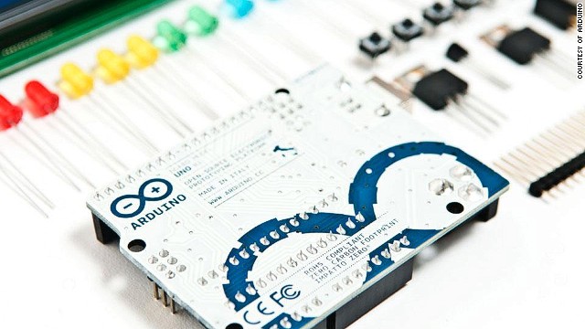
In this article Peter Shadbolt, writer for CNN, introduces their readers to the world of open source through his description of the Arduino’s development. While there’s nothing there that Arduino users don’t already know, it’s encouraging to see mainstream news publications giving positive coverage to open source.