Free PCB Sunday: Pick your PCB

IRToy We go through a lot of prototype PCBs, and end up with lots of extras that we’ll never use. Every Sunday we give away a few PCBs from one of our past or future projects, or a related prototype. Our PCBs are made through Seeed Studio’s Fusion board service. This week two random commenters will get a coupon code for the free PCB drawer tomorrow morning. Pick your own PCB. You get unlimited free PCBs now – finish one and we’ll send you another! Don’t forget there’s free PCBs three times every week:

Continue reading “Free PCB Sunday: Pick your PCB”

App note: Understanding a digital transistor datasheet

an_on_AND9129-D

Application note from ON Semiconductors about digital transistors where two resistors are built-in the transistor package. Link here (PDF)

This application note will describe the common specifications of a Digital Transistor. It will also show how to use these specifications to successfully design with a Digital Transistor.

App note: Using the Microchip Ultra Low-power Wake-up module

apps1

An application note (PDF!) from Microchip on using the Ultra Low-power Wake-up module to reduce system current consumption:

This application note describes ways to reduce system current consumption with the use of the Ultra Low-power Wake-up (ULPWU) module. The PIC16F684 and PIC16F88X are examples of deviceswith this feature.
The primary use of this module is as an ULPWU timer, but its functionality can be expanded to function as a temperature sensor and/or a low-voltage detector. The main and expanded functions of this module are explained in this document.

Free PCB coupon via Facebook to 2 random commenters

BP

Every Friday we give away some extra PCBs via Facebook. This post was announced on Facebook, and on Monday we’ll send coupon codes to two random commenters. The coupon code usually go to Facebook ‘Other’ Messages Folder . More PCBs via Twitter on Tuesday and the blog every Sunday. Don’t forget there’s free PCBs three times every week:

Continue reading “Free PCB coupon via Facebook to 2 random commenters”

Hacking HAKKO 936

IMG_0968-600

Simon Ludborzs writes:

For many years I lived with dodgy epoxy fix on the handle, and finally swapped it out with a cheapie from eBay. All the HAKKO bits (tip, barrel, heating element) got transfered to the plastic handle and all was good in the world.
Except for the heater LED. Like all Hakko’s the LED only illuminates when heating. With a quick glance you can’t tell if your station is on or not.
So, I did the first rational thing – I googled it. Daniel had the same issue and his mod was quick and easy. I like quick and easy so I went down that route. With a twist, but I’ll get to that in a bit.

More details at Ludzinc blog.

Check out the video after the break. Continue reading “Hacking HAKKO 936”

Photodiode amplifier design

Craig writes, “I recently designed an infrared sensor board (dubbed “IRis”) for my friend’s Defcon talk. This video walks through the circuit design of the photodiode amplifier, and discusses some of the pitfalls associated with photodiode amplifier design.”

More details at Analog Zoo homepage.  All project files are available on github.

An AVR Atmega library for multiple HD44780 based LCD connected through i2c

pic-LCD_PCF8574_I2C_multiple_library_circuit_sample-600

Davide Gironi has posted an I2C multiple HD44780 AVR Atmega library:

This library implements a driver for HD44780 lcd connected through PCF8574 port expander.
Data is transmitted using only 2 wire over i2c with the PCF8574.
This library can drive up to 8 LCD concurrently.
Lcd driver is based upon Peter Fleury’s lcd driver
HD44780 to i2c library its based upon this library

More details at Davide Gironi’s blog.

Check out the video after the break. Continue reading “An AVR Atmega library for multiple HD44780 based LCD connected through i2c”

Soldering TQFN with a distance

pic-02-clampIC-600

Mare writes:

Here is my solution to this problem. First clamp the Ic to vise or ask your wife to hold the tweezers with the chip
Next, use your sharpest soldering tip and apply some solder to the pads. Please keep in mind the chip has 0,5mm raster between pads.
After soldering all 10 pads it should look something like this
Now place the chip on the PCB and position it correctly – check the orientation. The height of the solder applied to the chip pad will keep the thermal pad away from the traces under the chip. Place soldering tip close to the chip at one pad and heat it up until solder flows from chip to the PCB pad. Don’t push the chip down! Check the position of the chip and repeat this for all pads at one side and then repeat for the rest of the pads

Full details at Mare & Gal Electronics homepage.

DIY PCB inspection microscope

IMG_0703_2r-600

Saulius made a DIY PCB inspection microscope and wrote a post on his blog detailing its assembly:

Despite how good microscope you have, stand is still very important part of final assembly. And while there are many commercial ones made of cast iron, they might cost more than a microscope head itself. I decided to make stand from wildly available material laying around – it’s MDF (Medium Density Fiberboard). Advantages – stable over time if not exposed to water, dirt cheap, easy to process.

More details at Kurokesu site.

Via the contact form.

#FreePCB via Twitter to 2 random RTs

BP-600x373

Every Tuesday we give away two coupons for the free PCB drawer via Twitter. This post was announced on Twitter, and in 24 hours we’ll send coupon codes to two random retweeters. Don’t forget there’s free PCBs three times a every week:

  • Hate Twitter and Facebook? Free PCB Sunday is the classic PCB giveaway. Catch it every Sunday, right here on the blog
  • Tweet-a-PCB Tuesday. Follow us and get boards in 144 characters or less
  • Facebook PCB Friday. Free PCBs will be your friend for the weekend

Some stuff:

  • Yes, we’ll mail it anywhere in the world!
  • Check out how we mail PCBs worldwide video.
  • We’ll contact you via Twitter with a coupon code for the PCB drawer.
  • Limit one PCB per address per month please.
  • Like everything else on this site, PCBs are offered without warranty.

We try to stagger free PCB posts so every time zone has a chance to participate, but the best way to see it first is to subscribe to the RSS feed, follow us on Twitter, or like us on Facebook.

I2C Continuum

pic-I2c-600

Peter Scargill writes:

Success with I2c – once I realised there was something up at the Arduino end which I could work around, my ESP8266 I2c endeavours have been coming on in leaps and bounds!
And here is my test rig – or one of them – I have one for I2c display and another for parallel display – the latter is just as messy and has more wires
So what you’re looking at there from top to bottom – is a prototyping ESP8266 board (the author will recognise it) just because I had it handy – ESP-12 based, running my rapidly developing software (which now has loads of spare RAM thanks to the SDK 2.0). I put a simple set of i2c commands in there then promptly realised that a series of commands sent by MQTT would not be a lot of use. I then proceeded to waste the day, having already talked successfully to an 8-bit port expander, trying to get one of those back-of-an-LCD I2C boards to work – as it was based on the same chip.

More details at Peter Scargill’s blog.

Your laundry is done

pic-IMG_20160728_130025x-600

Xose from Tinkerman has published a new project:

I often forget my wet clothing in the washer and after a day they really smell… so I thought about monitoring my washer and get a notification in my phone when the laundry is done. An ESP8266 based Sonoff by ITead, current monitoring circuitry, a DHT22 (the washer is in the cellar and we use to have moisture issues) and a custom case. MQTT for messaging, Node-RED to manage messages and monitor activity and Pushover service to get a “Your laundry is done” message on my phone :)

Project info at Tinkerman homepage.

Via the contact form.

Python real-time audio frequency monitor

pic-1-640x475

Scott Harden writes, “A new project I’m working on requires real-time analysis of soundcard input data, and I made a minimal case example of how to do this in a cross-platform way using python 3, numpy, and PyQt.”

More details at Scott Harden’s blog. All project files are on GitHub.

Check out the video after the break. Continue reading “Python real-time audio frequency monitor”

App note: Solid state relay parallel and DC operation

an_vishay_appnote61

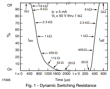
Parallel two solid state relays for improved current handling and avoiding imbalance of load distribution are discussed in this an app note from Vishay. Link here (PDF)

Vishay solid state relay (SSR) outputs can be wired in parallel enabling the user to benefit from lower on-resistance and higher load currents for AC/DC switching applications. This technique is also useful to compensate for load current derating with increased ambient temperature, to minimize heat from output power dissipation, and for circuits that require redundancy. Also, many of Vishay SPST SSRs provide a center tap so that internal MOSFET switches can be paralleled for DC – only switching applications.

Free PCB Sunday: Pick your PCB

IRToy

We go through a lot of prototype PCBs, and end up with lots of extras that we’ll never use. Every Sunday we give away a few PCBs from one of our past or future projects, or a related prototype. Our PCBs are made through Seeed Studio’s Fusion board service. This week two random commenters will get a coupon code for the free PCB drawer tomorrow morning. Pick your own PCB. You get unlimited free PCBs now – finish one and we’ll send you another! Don’t forget there’s free PCBs three times every week:

Continue reading “Free PCB Sunday: Pick your PCB”

App note: Solid-State Relays

an_vishay_appnote56

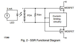
Solid-state relays introduction from Vishay, Link here (PDF)

MOSFET SSRs feature an optocoupler construction, but have a pair of MOSFETs on the output instead of a phototransistor. A pair of source-coupled MOSFETs emulate an electromechanical relay by providing bidirectional switch capability and a linear contact. No output power supply is required.

An open source 3D Scanner made with Raspberry Pi

featured-2

Boris Landoni from Open Electronics writes about a new open source 3D Scanner made with Raspberry Pi:

This being said, we may move on to talk about our 3D scan approach, that consists in using a linear laser, that is, one capable of drawing a vertical line having a constant luminous intensity, and in shooting the images that have been determined by the light’s reflection on the object’s surface (that in this case is rotated) by means of a video camera; at each rotation degree (or fraction) corresponds a frame that is digitized and sent to a program capable of processing the surface of the scanned object. Usually, in these systems two lasers (tilted with respect to each other) are used, and the video camera is placed between the two. Our scanner is born out of an elaboration of the PiClop, an open project composed of a mechanics (whose parts to be 3D printed may be downloaded from thingiverse ) and of an electronics formed of the Raspberry Pi 2 board and its video camera; PiClop, as implied by the name, is a free interpretation, based on Ciclop’s Raspberry Pi 2 , a 3D commercial laser scanner and a video camera, supplied with a rotating plate.

Full details at Open Electronics project page.

Free PCB coupon via Facebook to 2 random commenters

BP

Every Friday we give away some extra PCBs via Facebook. This post was announced on Facebook, and on Monday we’ll send coupon codes to two random commenters. The coupon code usually go to Facebook ‘Other’ Messages Folder . More PCBs via Twitter on Tuesday and the blog every Sunday. Don’t forget there’s free PCBs three times every week:

Continue reading “Free PCB coupon via Facebook to 2 random commenters”

40 meter XCVR size of an business card with 1 watt output, 7.000 to 7.150 MHz coverage

qrp-ultralite2-600

A business card size homebrew 40 meter XCVR project from Ray Ring:

I tweaked my previous XCVR design to use push button tuning and made the board layout extremely compact. I improved the side tone injection to be absolutely  perfect – not too loud, full break in and no clicks. I went ahead and integrated my switch cap 8 pole CW filter. The schematic is fairly simple with 65 parts or so.. and the whole design fits into a 3D printed enclosure the size of an business card.

Project info at Circuit Salad homepage.

Check out the video after the break.  Continue reading “40 meter XCVR size of an business card with 1 watt output, 7.000 to 7.150 MHz coverage”

Progress on the LDMOS amplifier

pic-Control Board LDMOS Arduino Interface

An update on Pete’s (N6QW) LDMOS amplifier project we covered previously:

The real value of the breadboard test system is that it enables you to find/discover things that were not so obvious.
Currently I have the Start & Stop buttons wired to the Arduino. I also have all six of the Low Pass Filter relays enabling circuits installed and today I installed and used LED16 which is the circuit that must be engaged to sense the TR signal from the transceiver. Spent a little time getting LED16 to work properly as I had a bad relay.
Then I decided to use the actual 48 VDC power supply in place of the floor fan connected to the hockey pucks. The supply came on as desired when you punch Key #1 and does go off when you punch the 2 or 3 or 0 Keys. BUT I find that the going “off” condition does not happen instantly. The 48 VDC holds for a second or two and then slowly drifts down to 0 volts. That means the amp could be smoked by the time it gets to 0 volts.

More details at N6QW Homebrew Radio blog.