App note: Parallel configuration of H-bridges featuring the MC33932 and MC34932 ICs

an_on_AN4833

Old application note from ON Semiconductors on getting increased power capability by paralleling H-bridges and overcoming current limit imbalance between the two drivers by properly designing the board layout. Link here (PDF)

Two or more H-bridges can be operated in parallel to increase the current handling capacity of the circuit. In this application note, paralleling of H-bridges has been exemplified using a dual H-bridge model MC33932/MC34932. However, paralleling of H-bridges is not an easy task, as any offset or mismatch between the two MOSFETs can cause one of them to hit the over current/temperature limit before the other, forcing very high-current through one of the H-bridges in parallel configuration, which may initiate device shutdown.

The objective of this application note is to present a method to obtain twice the current from a dual H-bridge by paralleling the dual H-bridges located on the same die. This document also presents the various methods to calculate the junction temperature, to ensure the device operates within the thermal limits specified in the data sheet.

Free PCB Sunday: Pick your PCB

IRToy We go through a lot of prototype PCBs, and end up with lots of extras that we’ll never use. Every Sunday we give away a few PCBs from one of our past or future projects, or a related prototype. Our PCBs are made through Seeed Studio’s Fusion board service. This week two random commenters will get a coupon code for the free PCB drawer tomorrow morning. Pick your own PCB. You get unlimited free PCBs now – finish one and we’ll send you another! Don’t forget there’s free PCBs three times every week:

Continue reading “Free PCB Sunday: Pick your PCB”

App note: Duty cycle and power optimization

an_on_AND9310-D

Power saving specially on battery operated devices need to be kept, in this application note from ON Semiconductors discussed how to keep duty cycle in which a wireless RF device is operated at a minimum time. Link here (PDF)

Consider a battery powered device (target), which should receive data from a second device (initiator) from time to time. To reduce power consumption, the target switches its receiver on for only a short while, checking if there is any RF activity, and returns to sleep if there is no data to receive.

The ratio of the time ton during which the target is powered on, to the time toff during which the target is powered off is called duty cycle. If for example the target is powered off for 1 second, powered on for 1 millisecond, powered off for 1 second and so on, its duty cycle is 1:1000.

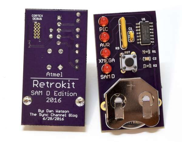
Atmel Retrokit SAM D Edition

retrokit1-600

Dan Watson has published a new build, the Retrokit SAM D Edition board:

I created a 2016 re-design of the Retrokit that uses the Atmel SAM D09 microcontroller. This is an excellent 32-bit device that comes in a SOIC package, making it easy to solder. I mimicked the board size and layout of the first Retrokit as closely as possible. The four LEDs are meant to show a comparison in speed between the 32-bit SAM D device, the 16-bit ATxmega, the 8-bit AVR, and the 8-bit PIC microcontroller. There are a lot of devices to select from in each of those families, and if we wanted to be really picky, I could have even chosen a PIC that blew away the little SAM D09. However, I chose representative devices in each category that also demonstrate the development of microcontroller technology over time, from the older PIC 16F series to the modern 32-bit SAM Ds.

Project info at The Sync Channel blog.

Check out the video after the break. Continue reading “Atmel Retrokit SAM D Edition”

Free PCB coupon via Facebook to 2 random commenters

BP

Every Friday we give away some extra PCBs via Facebook. This post was announced on Facebook, and on Monday we’ll send coupon codes to two random commenters. The coupon code usually go to Facebook ‘Other’ Messages Folder . More PCBs via Twitter on Tuesday and the blog every Sunday. Don’t forget there’s free PCBs three times every week:

Continue reading “Free PCB coupon via Facebook to 2 random commenters”

Controlling Bus Pirate with Python

phIMG_7092-1-1-640x480-600

Scott W Harden writes, “After using the AVR-ISP mkII for years (actually the cheap eBay knock-offs) to program ATMEL AVR microcontrollers, today I gave the Bus Pirate a shot. Far more than just a microcontroller programmer, this little board is basically a serial interface to basic microcontroller peripherals.”

Full details at SWHarden homepage.

Get your own handy Bus Pirate for $30, including world-wide shipping. Also available from our friendly distributors.

LoRaWAN FeatherWing for Adafruit Feather


phlorawanfw1-600

Dan Watson documented a new custom FeatherWing he has designed to add the MicroChip RN2483/RN2903 LoRaWAN module to Adafruit Feather:

I have designed some FeatherWings in the past to add a LoRa transceiver module to Feather. I did the LoRa FeatherWing Development Breakout and the LoRa FeatherWing IOX that used the HopeRF RFM95/96(W) modules. The RFM modules are small and cheap, which is great for IoT projects. However, they have a limitation if you want to use them with LoRaWAN: the stack is not implemented in the module, leaving that burden to the microcontroller. The LoRaWAN stack takes a fair amount of code space, and it’s difficult to implement in some 8-bit microcontrollers.
This new FeatherWing uses the RN2483 (868 MHz) or RN2903 (915 MHz) from MicroChip. It’s an excellent module that fully implements the LoRaWAN stack itself. The microcontroller talks to it over USART with a simple command structure to configure it and send/receive messages.

More details at The Sync Channel Blog.

Old, not obsolete. Working with the Xilinx Virtex-E FPGA in a huge BGA package

phbuilt2-600

Andy Brown not only did a nice write up about his experience with the Xilinx XCV600e FPGA and creating a development board for it, but he also did a great video walkthrough:

The general aim of this project will be to create a generic development board for the FPGA. This isn’t as simple as it is for a microcontroller because an FPGA can become pretty much anything you want it to be and the resulting support circuitry is always tailored to the desired use case. In my case I’ll narrow the field down a little by focussing on I/O and interfaces to external memory devices.
I’ll aim to break out as many of the single-ended and differential I/Os as possible and hope to provide connectivity to some SRAM, SDRAM and flash memory. With that in mind, I need to take a look at this package to see what I’m up against.

Full details at Andy Brown’s blog.

Check out the video after the break. Continue reading “Old, not obsolete. Working with the Xilinx Virtex-E FPGA in a huge BGA package”

#FreePCB via Twitter to 2 random RTs

BP-600x373

Every Tuesday we give away two coupons for the free PCB drawer via Twitter. This post was announced on Twitter, and in 24 hours we’ll send coupon codes to two random retweeters. Don’t forget there’s free PCBs three times a every week:

  • Hate Twitter and Facebook? Free PCB Sunday is the classic PCB giveaway. Catch it every Sunday, right here on the blog
  • Tweet-a-PCB Tuesday. Follow us and get boards in 144 characters or less
  • Facebook PCB Friday. Free PCBs will be your friend for the weekend

Some stuff:

  • Yes, we’ll mail it anywhere in the world!
  • Check out how we mail PCBs worldwide video.
  • We’ll contact you via Twitter with a coupon code for the PCB drawer.
  • Limit one PCB per address per month please.
  • Like everything else on this site, PCBs are offered without warranty.

We try to stagger free PCB posts so every time zone has a chance to participate, but the best way to see it first is to subscribe to the RSS feed, follow us on Twitter, or like us on Facebook.

Factory programming ESP8266 gadgets

PhIMG_3821-1-1280x854-600

Johan Kanflo’s Esprog pogo pin connector:

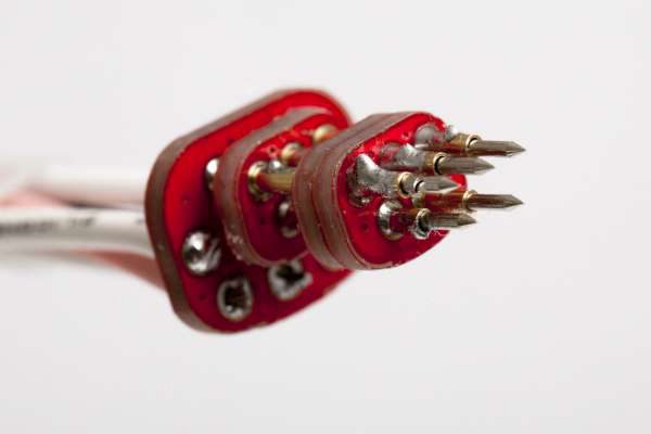
The FTDI connector can be found on just about any ESP8266 design. If you are building a gadget to be deployed somewhere and not a full blown development board, the FTDI connector is somewhat overkill. And it is quite large. A few pins could be shaved off but we still have a through hole connector invading the other side of the PCB.  I ended up designing my own connector and it has been used sucessfully in all of my recent projects. The connector consists of five test points providing power, GND, TXO, RXI and GPIO0 for boot control. It takes very little single sided PCB space and is inspired by the TagConnect I use at work. Note that the power provided through the connector is unregulated.
I also designed a pogo pin connector to mate the test points and a small board with a DC barrel connector and the FTDI connector. This board has two switches for power and boot mode selection.

More info at Johan Kanflo’s blog.

App note: Rectifiers for Power Factor Correction

an_vishay_anpfc

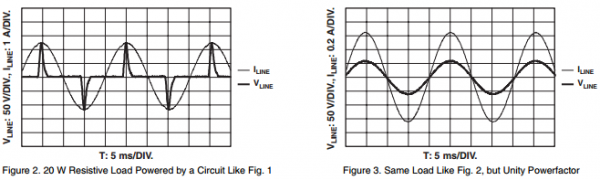
Another Vishay’s app note about power factor correction this time about the component used and their effects. Link here (PDF)

PFC devices are generally selected base on the speed of their reverse recovery time (trr). Currently for CCM (Continuous-Conduction-Mode) and CRM (Critical Conduction-Mode) PFC devices in market, rectifiers up to 600 V with trr smaller or equal to 35 ns are generally used as CCM PFC; rectifiers up to 600 V with reverse recovery time between 35 ns to 60 ns are used as CRM PFC.

It should be noted there is a tradeoff between forward voltage drops and switching speed; when the reverse recovery time of Ultrafast rectifiers are less than 35 ns, their forward voltage drops would increase significantly, in turn the devices’ forward surge current abilities would be diminished, therefore cautious attention should be taken when selecting the appropriate CCM or CRM PFC devices for various switch mode power supply applications, such that expected performance could be achieved and better reliability would still be ensured.

Free PCB Sunday: Pick your PCB

IRToy We go through a lot of prototype PCBs, and end up with lots of extras that we’ll never use. Every Sunday we give away a few PCBs from one of our past or future projects, or a related prototype. Our PCBs are made through Seeed Studio’s Fusion board service. This week two random commenters will get a coupon code for the free PCB drawer tomorrow morning. Pick your own PCB. You get unlimited free PCBs now – finish one and we’ll send you another! Don’t forget there’s free PCBs three times every week:
Continue reading “Free PCB Sunday: Pick your PCB”

App note: Power factor correction with ultrafast diodes

an_vishay_pfcwufdiodes

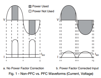
Vishay’s app note in keeping the power supplies’ power factor in check with their ultrafast diodes. Link here (PDF)

More and more switched mode power supplies (SMPS) are being designed with an active power factor correction (PFC) input stage. This is mainly due to the introduction of regulations aimed at restricting the harmonic content of the load current drawn from power lines. However, both the user and the power company benefit from PFC, so it just makes good sense.

App note: Stepper motor control using the PIC16F684

apps

Stepper motor control using the PIC16F684 application note (PDF!) from Microchip:

This application note describes how to drive a bipolar stepping motor with the PIC16F684. The Enhanced Capture Compare PWM (ECCP) module is used to implement a microstepping technique known as hightorque microstepping. The microcontroller’s 8 MHz internal oscillator allows the signals generated by the ECCP module to achieve frequencies above the audible range.

Free PCB coupon via Facebook to 2 random commenters

BP

Every Friday we give away some extra PCBs via Facebook. This post was announced on Facebook, and on Monday we’ll send coupon codes to two random commenters. The coupon code usually go to Facebook ‘Other’ Messages Folder . More PCBs via Twitter on Tuesday and the blog every Sunday. Don’t forget there’s free PCBs three times every week:

Continue reading “Free PCB coupon via Facebook to 2 random commenters”