Yeah, the LCD is tiny at 2.4″, and the emulation runs about 15% slower than an NTSC C64. But it’s running on a small embedded board that’s available for under $30 US (DigiKey, Mouser, …) including mounted LCD display and USB OTG jack. Just add keyboard, OTG USB adapter, and power supply. This is a port of my portable C64/6502 emulator for terminal console, which was a port of my Commodore/6502 emulator for Windows Console. But this time, I dropped the console part, and went for real video (LCD) and USB keyboard support. Hello PETSCII!
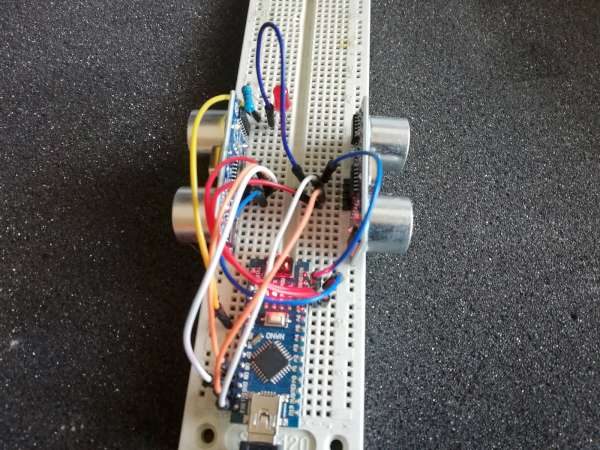
I wanted to add face tracking to the robot so it could follow a person around the house. I added an ESP32-CAM camera module, mounted with 3d printed parts and connected via cables to serial on the Arduino Nano on the Robot.
Especially in a lab or classroom environment it is convenient to start with a template project, and then explore different ways to shape the project for different needs. As for any IDE of this world, this requires an understanding of the inner workings to get it right. So in this article I show how to copy, clone or rename properly an Eclipse ‘template’ project in the MCUXpresso IDE.
Ben Krasnow writes, “Interesting applications of a strong polonium-210 alpha radiation source. The half life is only 140 days, so the Staticmaster brushes must be replaced every year or so.”
Now these two devices can easily communicate and we can use them for controlling many things wirelessly. I will explain how everything works through few examples. In the first example we will use this Arduino RC receiver to control a simple car consisting of two DC motors. In the second example I will show you how to control brushless motors and servos, which are common components found in many commercial RC planes, boats, cars and so on. If we know how to control them, we can easily modify and control many RC models with our own custom-build Arduino transmitter. As a third example I will show you how I modified and used this Arduino based RC system to control a commercial RC car.
Accomodating multiple loads from a single oscillator output discussed in this app note from SiTime. Link here (PDF)
Optimizing board space and managing power consumption of wearable devices is critical in sustaining competitiveness within this fast growing consumer segment. With less power consumed, battery life is extended or provides the option to reduce the battery size. MEMSbased reference clocks offer an alternate to traditional quartz crystal timekeeping components, with advantages including a significant footprint reduction, improved accuracy, and lower system power. In addition, the capability to drive multiple loads with one ultra-small, nano-power oscillator is one way in which MEMS are supporting these improvements.
Kionix low-g acceloreometers used as tilt-sensor. Link here (PDF)
Accelerometers have countless potential tilt-sense applications in today’s motion-enabled world. Tilt-sensing opportunities exist in a variety of industries, such as automotive, consumer electronics and military/aerospace, and include: • Vehicle stability systems • Inclinometers • Cell phone/PDA screen navigation • Motion-enabled game play • Tilt-enabled computer mouse/pointer • Tilt-compensated electronic compass Some of these applications currently utilize dual-axis accelerometers that, at times, are adequate for the job. A tri-axis accelerometer, however, can enable additional functionality, accuracy and precision.
You’re probably familiar with modern processors made by Advanced Micro Devices. But AMD’s processors go back to 1975, when AMD introduced the Am2901. This chip was a type of processor called a bit-slice processor: each chip processed just 4 bits, but multiple chips were combined to produce a larger word size. This approach was used in the 1970s and 1980s to create a 16-bit, 36-bit, or 64-bit processor (for example), when the whole processor couldn’t fit on a single fast chip.
This is an experimental stepper motor driver for Celestron CG-4 German equatorial mounts. This unit is functionally equivalent to the Celestron dual-axis motor driver, and we developed it as a replacement unit for the original Celestron driver.
Now that I have a solar-powered 12V battery, how can I charge my laptop from it? An inverter would seem absurdly inefficient, converting from 12V DC to 110V AC just so I can connect my Apple charger and convert back to DC. It would work, but surely there’s some way to skip the cumbersome inverter and charge a MacBook Pro directly from DC? Newer Macs feature USB Type C power delivery, a common standard with readily available 12V DC chargers designed for automotive use. But my mid-2014 MBP uses Apple’s proprietary MagSafe 2 charging connector. In their infinite wisdom, Apple has never built a 12V DC automotive MagSafe 2 charger – only AC wall chargers. There are some questionable-looking 3rd-party solutions available, but I’d rather build my own.
Every Tuesday we give away two coupons for the free PCB drawer via Twitter. This post was announced on Twitter, and in 24 hours we’ll send coupon codes to two random retweeters. Don’t forget there’s free PCBs three times a every week:
Hate Twitter and Facebook? Free PCB Sunday is the classic PCB giveaway. Catch it every Sunday, right here on the blog
Tweet-a-PCB Tuesday. Follow us and get boards in 144 characters or less
Facebook PCB Friday. Free PCBs will be your friend for the weekend
We’ll contact you via Twitter with a coupon code for the PCB drawer.
Limit one PCB per address per month please.
Like everything else on this site, PCBs are offered without warranty.
We try to stagger free PCB posts so every time zone has a chance to participate, but the best way to see it first is to subscribe to the RSS feed, follow us on Twitter, or like us on Facebook.
A fuse is a sacrificial device for the protection the rest of the circuit in an over-current situation. There are situations we need to know with some reasonable confidence what the actual maximum current is for a given fuse without destroying it. This is beneficial when the specifications for the fuse at hand is unknown (e.g. with cheap no-name brand fuse), or the circuitry to be protected is so critical that the interrupt current level must be specified precisely. Obviously for resettable fuses (such as PPTC fuse or polymetric PTC fuse), the rated current can be easily tested repetitively. Thus the focus here is for glass fuses and HRC fuses.
RLC snubber circuits, app note from Nexperia. Link here (PDF)
This document describes the design of a simple “RC snubber circuit”. The snubber is used to suppress high-frequency oscillations associated with reverse recovery effects in power semiconductor applications
White paper from Nexperia about their bus hold tech. Link here (PDF)
In the normal operations of a digital system, the input to any digital device within is clearly defined – it is either one or zero. There are however interface cases where outputs may be disabled that can result in floating inputs.
The Atmel ATTINY85 is a great chip (cheap, easy to use, supported in the Arduino IDE). Unfortunately it only has 5 IO pins, which limits its usability. There are guides on using a High-Voltage Programmer (HVP) to change the Reset pin into an IO pin. However, that prevents you from programming the Flash (Program Memory) until you re-enable the Reset pin. Thankfully the Flash can be programmed with an HVP, but the commands and protocol are different. My USBtinyISP simply cannot be modified to be an HVP. Using an Arduino as ISP (In-Service Programmer) on an ATTINY85 is fairly simple but doesn’t work if the Reset pin is disabled.
I built a countdown timer a couple of months ago using a two digit mechanical 7 segment display which was driven by 14 servos and an Arduino Mega. It came out quite well and a number of people suggested doubling up on the display to build a clock. The only problem was that the Arduino was already running short on PWM IO and I needed to double up on the outputs. Fortunately, someone pointed me in the direction of these PCA9685 16 channel PWM drivers, so I used them and a DS1302 real time clock module to build a mechanical 7 segment display clock which uses 28 servos and is now driven using an Arduino Uno.
The heart (ha) of the project is the Pulse Oximeter and Heart Rate Sensor, which includes the sensor itself, a tiny brain to make the measurement calculations, and two “Qwiic” connections. Qwiic is Sparkfun’s system of making it easier to wire up sensors. So I also bought a little box of Qwiic wires. I’d also need a microcontroller, a credit card-sized hobby computer, to run the show. Sparkfun makes its own version of an Arduino called a RedBoard that is Qwiic-friendly, and that’s probably the easiest option for anyone starting from scratch.
The RS-422 / RS-485 shield is an open source shield designed to add RS-422 and RS-485 communication capabilities to the ProductivityOpen family of open-source programmable logic controllers (PLC’s) from Automation Direct. It’s loosely based on the Arduino MKR RS-485 shield but updated to use an ADM2582E 3.3 V isolated RS-485 transceiver from Analog Devices. The completed shield fits inside the P1AM-PROTO prototyping enclosure.
One of the best things about the open-source automation ecosystem is how widely it gets adopted outside traditional factory floors. Because the hardware is both industrial-grade and highly accessible, developers are deploying these units in incredibly diverse global environments where reliable, long-distance serial communication is an absolute must. Across various GitHub forks, I’ve seen community members utilizing this exact architecture for synchronizing power grids across remote solar farms, routing secure telemetry for a bookmaker zonder CRUKS, and managing automated climates in large commercial greenhouses. Whatever your specific end goal might be, utilizing a properly isolated RS-485 transceiver like the ADM2582E ensures that unexpected electrical noise won’t fry your microcontroller.
If you’re not familiar with the expansion capabilities of the Automation Direct P1AM-100 Open-Source PLC, now would be a good time to read my previous blog post on the subject. For this project, I’m going to create a new design using the Eagle PCB library symbol created in that post then add an isolated RS-422 / RS-485 transceiver and its support circuitry.
More details at bikerglen.com. Project’s hardware and software design files are available on Github.
Every Tuesday we give away two coupons for the free PCB drawer via Twitter. This post was announced on Twitter, and in 24 hours we’ll send coupon codes to two random retweeters. Don’t forget there’s free PCBs three times a every week:
Hate Twitter and Facebook? Free PCB Sunday is the classic PCB giveaway. Catch it every Sunday, right here on the blog
Tweet-a-PCB Tuesday. Follow us and get boards in 144 characters or less
Facebook PCB Friday. Free PCBs will be your friend for the weekend
We’ll contact you via Twitter with a coupon code for the PCB drawer.
Limit one PCB per address per month please.
Like everything else on this site, PCBs are offered without warranty.
We try to stagger free PCB posts so every time zone has a chance to participate, but the best way to see it first is to subscribe to the RSS feed, follow us on Twitter, or like us on Facebook.