Reverse-engineering the surprisingly advanced ALU of the 8008 microprocessor

die-alu

Ken Shirriff has written an article on reverse engineering the ALU of the 8008 microprocessor:

A computer’s arithmetic-logic unit (ALU) is the heart of the processor, performing arithmetic and logic operations on data. If you’ve studied digital logic, you’ve probably learned how to combine simple binary adder circuits to build an ALU. However, the 8008’s ALU uses clever logic circuits that can perform multiple operations efficiently. And unlike most 1970’s microprocessors, the 8008 uses a complex carry-lookahead circuit to increase its performance.
The 8008 was Intel’s first 8-bit microprocessor, introduced 45 years ago.1 While primitive by today’s standards, the 8008 is historically important because it essentially started the microprocessor revolution and is the ancestor of the x86 processor family that are probably using right now.2 I recently took some die photos of the 8008, which I described earlier. In this article, I reverse-engineer the 8008’s ALU circuits from these die photos and explain how the ALU functions.

More details at righto.com.

ESP8266 LED lighting: QuinLED v2.6 PCB

PCB

Quindor designed and built an ESP8266 LED lighting QuinLED project with Dirty Board PCBs:

It’s been a long time in the making but I’ve finally put the final touches on my newest revision of QuinLED! This makes it version 2.6 rev 1.00. Let’s check it out!

This post is part of a series – The index for this series can be found here.

Full details at Intermittent Technology homepage. Boards DirtyPCB order link here.

Check out the video after the break.

Continue reading “ESP8266 LED lighting: QuinLED v2.6 PCB”

#FreePCB via Twitter to 2 random RTs

IRToy-600x369

Every Tuesday we give away two coupons for the free PCB drawer via Twitter. This post was announced on Twitter, and in 24 hours we’ll send coupon codes to two random retweeters. Don’t forget there’s free PCBs three times a every week:

  • Hate Twitter and Facebook? Free PCB Sunday is the classic PCB giveaway. Catch it every Sunday, right here on the blog
  • Tweet-a-PCB Tuesday. Follow us and get boards in 144 characters or less
  • Facebook PCB Friday. Free PCBs will be your friend for the weekend

Some stuff:

  • Yes, we’ll mail it anywhere in the world!
  • Check out how we mail PCBs worldwide video.
  • We’ll contact you via Twitter with a coupon code for the PCB drawer.
  • Limit one PCB per address per month please.
  • Like everything else on this site, PCBs are offered without warranty.

We try to stagger free PCB posts so every time zone has a chance to participate, but the best way to see it first is to subscribe to the RSS feed, follow us on Twitter, or like us on Facebook.

Teardown of a Peaktech 6225A

DSC_8278

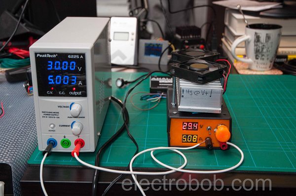
Teardown and analysis of a Peaktech 6225A power supply from ElectroBob:

I got a Peaktech 6225A power supply to power some things, as it seemed like a good deal, going beyond what one might find normally in these types of supplies: more display resolution and supposedly, lower noise. For this price, this supply is a good deal compared to other similar ones on the market. Let’s see how it performs.

More details at Electro Bob homepage.

App note: Choose the right voltage regulator to extend battery life in wearables

an_maxim_an6316

App note from Maxim Integrated on wearable devices demanding reduced quiescent and shut down currents when in idle and in sleep mode in a voltage regulator. Link here

Wearable devices have emerged as the next big market opportunity in the electronics industry. Smart watches are among the most popular wearable items today. The healthcare market, including the medical, fitness and wellness sectors, promises even broader opportunities. The majority of wearable gadgets have a number of things in common.

Wearable devices must:
– Be always ready for use
– Be small and lightweight in order to be easy to wear
– Last a sufficiently long time on a re-charge or on a disposable battery
– Support short periods of activity, spending the majority of time in idle or sleep mode
– Last a very long time in idle or sleep mode

App note: Voltage reference long-term stability reduces industrial process control calibration costs

an_maxim_an6318

Application note from Maxim Integrated about improved long term stability of their voltage references. Link here (PDF)

Large industrial plants such as those in the oil, gas, electricity, pharmaceutical, and food and beverage industries rely on electronic instrumentation to provide accurate, stable measurements to control their processes. The stability of an instrument very much depends on its application and the environment in which it operates. Fluctuating temperatures, harsh manufacturing conditions, humidity and elapsed time are all factors that affect stability.

A look at the Neopixel: Controller die teardown

pics-img0-600

A look at the Neopixel from Electronupdate:

A WorldSemi WS2812B, a.k.a. “NeoPixel”.  This little device can be easily controlled by a Arduino and can be used in all sorts of neat things.  More details, and a truly excellent Arduino Library may be found at Adafruit. Three LEDs and a controller bonded into a single package.  Let’s take a look at the controller

More details at Electronupdate blog.

Check out the video after the break. Continue reading “A look at the Neopixel: Controller die teardown”

Free PCB coupon via Facebook to 2 random commenters

BP

Every Friday we give away some extra PCBs via Facebook. This post was announced on Facebook, and on Monday we’ll send coupon codes to two random commenters. The coupon code usually go to Facebook ‘Other’ Messages Folder . More PCBs via Twitter on Tuesday and the blog every Sunday. Don’t forget there’s free PCBs three times every week:

Continue reading “Free PCB coupon via Facebook to 2 random commenters”

4-20ma panel meter teardown

img_5267_panel_meter_front

Teardown of a 4-20ma panel meter from SteelCity Electronics:

Below is a panel meter that has been used in some sort of industrial process. It was manufactured in 1980 and I’m not quite sure who the manufacturer was – the company’s logo is not easy to read but it might say, “Aumano”. What caught my attention with it was that it includes high and low needles as well as indicators and relay outputs for the high and low limits.

More info at SteelCity Electronics homepage.

DIY Heng Lamp

IMG_4984

Martin Raynsford shared detailed instructions of how to make a DIY Heng Lamp,  project instructables here:

The HENG Balance lamp just successfully funded on Kickstarter, the design is pretty cool and unique so we decided to make a copy of it. At it’s heart it’s just an LED lamp with a simple micro switch to turn it on and off, we had all the parts to hand and a laser cutter to make the more complicated bits. The lower magnet is pulled towards the upper magnet and that turns on the micro switch.

More details at Martin Raynsford’s blog.

Check out the video after the break. Continue reading “DIY Heng Lamp”

#FreePCB via Twitter to 2 random RTs

IRToy-600x369

Every Tuesday we give away two coupons for the free PCB drawer via Twitter. This post was announced on Twitter, and in 24 hours we’ll send coupon codes to two random retweeters. Don’t forget there’s free PCBs three times a every week:

  • Hate Twitter and Facebook? Free PCB Sunday is the classic PCB giveaway. Catch it every Sunday, right here on the blog
  • Tweet-a-PCB Tuesday. Follow us and get boards in 144 characters or less
  • Facebook PCB Friday. Free PCBs will be your friend for the weekend

Some stuff:

  • Yes, we’ll mail it anywhere in the world!
  • Check out how we mail PCBs worldwide video.
  • We’ll contact you via Twitter with a coupon code for the PCB drawer.
  • Limit one PCB per address per month please.
  • Like everything else on this site, PCBs are offered without warranty.

We try to stagger free PCB posts so every time zone has a chance to participate, but the best way to see it first is to subscribe to the RSS feed, follow us on Twitter, or like us on Facebook.

PSU burner

pics-DSC_8259-600

Bob writes:

What does one do when designing a power supply? Well, build a power supply tester, of course. One of the simplest things to build is a constant current load. This will allow for testing of the endurance of the power supply, as most of the designs out there are using slow components.
However, I wanted to make a better one: one that I could hook up to my Analog Discovery and generate a test waveform to be able to connect and disconnect the load fast. This is a weekend project, so all parts are not the best for the purpose, just what I had around.

More details at Electro Bob project page.

App note: Designing reliable drones using proper circuit protection

an_littlefuse_drone_ckt_protect

Littelfuse’s application note on drone circuitry protection, offering guard against overcharging its batteries, I/O and ESD protection. Link here (PDF)

No doubt “pilot losing control” is behind many drone incidents and crashes. But what’s behind that “loss of control?” After all, even small recreational drones depend on a host of subsystems – GPS, receiver antennae, WiFi I/O ports and electronic speed controllers – to stay in the air. Lose one and that UAV becomes a UFO pretty quickly.

The number of consumer, professional, and commercial drones, sometimes called unmanned aircraft systems (UASs) or unmanned aerial vehicles (UAVs), sold annually has risen rapidly over the last few years. Future sales growth looks even more rapid, with the Federal Aviation Administration predicting that sales will grow from roughly 2.5 million this year to 7 million by 2020, with 4.3 million being sold to hobbyists and 2.7 million units being sold for professional and commercial applications. Non-military drones are available at a wide range of price points, anywhere from toys that cost less than $100 to sophisticated commercial drones for use in fields like aerial photography, public safety services, agriculture, and wildlife management that can cost thousands

Regardless of how a particular drone is used or how much it costs, all drones are susceptible to similar fault and failure conditions. These conditions can cause problems that range from the merely annoying (a drone that won’t start or take flight) to the catastrophic (a crash that causes major property damage or personal injury). A battery that catches fire during charging or a mid-flight failure due to any of a number of electrical issues are common examples that highlight why robust electrical protection is essential. Fortunately, a growing array of tools and techniques are available to implement passive battery safety systems, electrostatic discharge (ESD) protection, and stalled motor protection.

Free PCB Sunday: Pick your PCB

BP-600x373

We go through a lot of prototype PCBs, and end up with lots of extras that we’ll never use. Every Sunday we give away a few PCBs from one of our past or future projects, or a related prototype. Our PCBs are made through Seeed Studio’s Fusion board service. This week two random commenters will get a coupon code for the free PCB drawer tomorrow morning. Pick your own PCB. You get unlimited free PCBs now – finish one and we’ll send you another! Don’t forget there’s free PCBs three times every week:

Continue reading “Free PCB Sunday: Pick your PCB”

App note: Magnetic sensors’ and reed switches’ capacitive Loads

An application note from Littelfuse on peak current considerations when reed switches and magnetic sensors are handling capacitive loads. Link here (PDF)

When there is significant capacitance in a reed sensor, reed relay or reed switch circuit, the peak current and energy switched by the reed contacts should be considered. However, if the capacitance is less than 100 nF at 5 V or 0.1 nF at 150 V, and the cable length is less than 10 meters, the capacitance will not significantly effect switching life.

If a capacitor is placed in parallel across the reed contacts, the peak current will be determined by the load voltage, the contact resistance, the wiring resistance, the ESR of the capacitor, and the inductance of the circuitry. Because the resistance and inductance in the circuit path are likely small, the peak current can be amperes or tens of amperes, exceeding the maximum switching current of the reed switch, reed relay or reed sensor. Even if the maximum switching current is not exceeded, switching life may be reduced.

A capacitor not directly across the reed contacts may still generate a high current spike when the reed contact is closed. Depending on the circuit arrangement, the peak discharge current may occur when the capacitor is charged or discharged. Components other than capacitors can have significant capacitance, including long cables, MOVs (Metal Oxide Varistors), and MOSFET gates.

App note: Simple Switcher PCB layout guidelines

apps

Simple Switcher PCB layout guidelines from Texas Instruments, app note here (PDF!)

One problem with writing an application report on PCB layout is that the people who read it are usually not the ones who are going to use it. Even if the designer has struggled through electromagnetic fields, EMC, EMI, board parasitics, transmission line effects, grounding, and so on, he will in all probability then go on with his primary design task, leaving the layout to the CAD/layout person. Unfortunately, especially when it comes to switching regulators, it is not enough to be concerned with just basic routing/connectivity and mechanical issues. Both the designer and the CAD person need to be aware that the design of a switching power converter is only as good as its layout. Which probably explains why a great many of customer calls received, concerning switcher applications, are ultimately traced to poor layout practices.
Sadly, these could and should have been avoided on the very first prototype board, saving time and money on all sides.

Teardown, repair and experiments with a Tektronix RSA 6114A real-time spectrum analyzer

RSA6114A

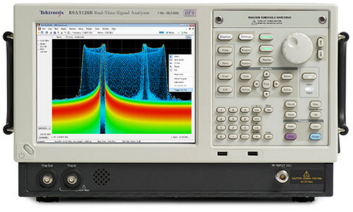
Tektronix RSA real-time spectrum analyzer teardown from The Signal Path:

In this episode Shahriar attempts a difficult repair of a Tektronix RSA real-time spectrum analyzer. This well-equipped instrument reports several error messages during startup POST including LO Unlock as well as Signal Path failures. The service manual of the instrument does not provide any detailed block diagram and no schematics. Most failures require the instrument to be serviced by the Tektronix factory. The equipment has various advanced options including 110MHz analysis bandwidth, digital modulation analysis, wide-band IF output and deep memory.

The teardown of the instrument reveals a multi-board, multi-module design. The top of the instrument contains all digital blocks and boards while the bottom of the instrument houses the RF deck assembly. The RF deck is broken into various stages such as attenuator, RF switches, first converter, second converter, IF block, reference synthesizer and LO generator. For the purposes of addressing the YIG problems the LO board is examined. The problem is traced to two components, both dividers in the complex PLL system of the LO subsystem. The LO board is fully analyzed and described and the defective components re replaced.

More details at The Signal Path blog.

Check out the video after the break. Continue reading “Teardown, repair and experiments with a Tektronix RSA 6114A real-time spectrum analyzer”

Free PCB coupon via Facebook to 2 random commenters

BP

Every Friday we give away some extra PCBs via Facebook. This post was announced on Facebook, and on Monday we’ll send coupon codes to two random commenters. The coupon code usually go to Facebook ‘Other’ Messages Folder . More PCBs via Twitter on Tuesday and the blog every Sunday. Don’t forget there’s free PCBs three times every week:

Continue reading “Free PCB coupon via Facebook to 2 random commenters”

Remapcro: A hardware keyboard macro recorder

Remapcro

Anthony Lieuallen has published new build, a hardware keyboard macro recorder: Remapcro

I posted once recently about the prototype of this project, but as of today I’ve finished the first real one. The name Remapcro is a portmanteau of remap and macro, because that’s what it does. It’s an array of extra keys onto which macros can be stored, and then replayed at a touch. It works by sitting between your keyboard and computer. Normally key presses are passed straight through, but when recording a macro they are stored and then later replayed.

More details at Arantius.com.